

- •Textbook Series
- •Contents
- •1 Definitions
- •Introduction
- •Abbreviations
- •Definitions
- •2 International Agreements and Organizations
- •The Chicago Convention
- •International Law
- •Commercial Considerations
- •Customs and Excise, and Immigration
- •International Obligations of Contracted States
- •Duties of ICAO Member States
- •Status of Annex Components
- •The International Civil Aviation Organization (ICAO)
- •The Organization of ICAO
- •Regional Structure of ICAO
- •Regional Structure and Offices
- •ICAO Publications
- •Other International Agreements
- •The Conventions of Tokyo, the Hague and Montreal
- •The Warsaw Convention
- •The Rome Convention
- •IATA
- •ECAC
- •EASA
- •Eurocontrol
- •World Trade Organization
- •Geneva Convention
- •EU Regulation 261/2004
- •Questions
- •Answers
- •3 Airworthiness of Aircraft
- •Introduction
- •Airworthiness
- •Questions
- •Answers
- •4 Aircraft Nationality and Registration Marks
- •Introduction
- •Nationality and Registration Marks
- •Certification of Registration
- •Aircraft Markings
- •Classification of Aircraft
- •Questions
- •Answers
- •5 Flight Crew Licensing
- •Introduction
- •Definitions
- •General Rules Concerning Licensing
- •Licences and Ratings for Pilots
- •Multi-crew Pilot Licence (MPL)
- •Instrument Rating (Aeroplane) (IR(A))
- •Instructor and Examiner Rating
- •JAR-FCL 3 Medical Requirements
- •Pilot Proficiency
- •EASA Theoretical Knowledge Examinations
- •Questions
- •Answers
- •6 Rules of the Air
- •History
- •Applicability of the Rules of the Air
- •General Rules
- •Visual Flight Rules
- •Instrument Flight Rules
- •Semi-circular Flight Level Rules and RVSM
- •Special VFR
- •Distress and Urgency Signals
- •Restricted, Prohibited or Danger Areas
- •Signals for Aerodrome Traffic
- •Marshalling Signals
- •Flight Deck Signals
- •Questions
- •Answers
- •Instrument Procedures
- •PANS OPS
- •Instrument Departure Procedures
- •Questions
- •Answers
- •8 Approach Procedures
- •Procedure Basics
- •Approach Procedure Design
- •Obstacle Clearance Altitude/Height
- •Operating Minima
- •Descent Gradients
- •Track Reversal and Racetracks
- •Missed Approach Segment and Procedure
- •Published Information
- •RNAV Approach Procedures based on VOR/DME
- •Questions
- •Answers
- •9 Circling Approach
- •Circling Approach
- •Questions
- •Answers
- •10 Holding Procedures
- •Holding Procedures
- •Entry Sectors
- •ATC Considerations
- •Obstacle Clearance
- •Questions
- •Answers
- •11 Altimeter Setting Procedure
- •Altimeter Setting Objectives
- •Transition
- •Phases of Flight
- •Questions
- •Answers
- •12 Parallel or Near-parallel Runway Operation
- •Safety
- •Runway Spacing
- •Questions
- •Answers
- •13 SSR and ACAS
- •Airborne Collision Avoidance System (ACAS)
- •Questions
- •Answers
- •14 Airspace
- •Introduction
- •Control Areas and Zones
- •Classes of Airspace
- •Required Navigation Performance (RNP)
- •Airways and ATS Routes
- •Questions
- •Answers
- •15 Air Traffic Services
- •Introduction
- •Air Traffic Control
- •ATC Clearances
- •Control of Persons and Vehicles at Aerodromes
- •The Flight Information Service
- •The Alerting Service
- •Procedures
- •Questions
- •Answers
- •16 Separation
- •Concept of Separation
- •Vertical Separation
- •Horizontal Separation
- •Radar Separation
- •Procedural Wake Turbulence Separation
- •Radar Wake Turbulence Separation
- •Visual Separation in the Vicinity of Aerodromes
- •Stacking
- •Questions
- •Answers
- •17 Control of Aircraft
- •Procedural ATC
- •Radar Control
- •Radar Identification
- •Radar Service
- •Aerodrome Control
- •Approach Control Service
- •Air Traffic Advisory Service
- •Aircraft Emergencies
- •Questions
- •Answers
- •18 Aeronautical Information Service (AIS)
- •Introduction
- •General
- •The Integrated Aeronautical Information Package
- •The Aeronautical Information Publication (AIP)
- •Notices to Airmen (NOTAM)
- •SNOWTAM
- •ASHTAM
- •Aeronautical Information Circulars (AICs)
- •Pre-flight and Post-flight Information
- •Questions
- •Answers
- •Introduction
- •Aerodrome Reference Code
- •Glossary of Terms
- •Aerodrome Data
- •Runways
- •Taxiways
- •Aprons
- •Questions
- •Answers
- •Requirements
- •Visual Aids for Navigation
- •Runway Markings
- •Taxiway Markings
- •Signs
- •Markers
- •Visual Docking Guidance Systems
- •Questions
- •Answers
- •21 Aerodrome Lighting
- •Aerodrome Lights
- •Approach Lighting Systems
- •Runway Lighting
- •Taxiway Lighting
- •Questions
- •Answers
- •22 Obstacle Marking and Aerodrome Services
- •Introduction
- •Visual Aids for Denoting Obstacles
- •Visual Aids for Denoting Restricted Use Areas
- •Emergency and Other Services
- •Other Aerodrome Services
- •Questions
- •Answers
- •23 Facilitation
- •Entry and Departure of Aircraft
- •Questions
- •Answers
- •24 Search and Rescue
- •Definitions and Abbreviations
- •Establishment and Provision of SAR Service
- •Co-operation between States
- •Operating Procedures
- •Questions
- •Answers
- •25 Security
- •Introduction
- •Objectives
- •Organization
- •Preventative Security Measures
- •Management of Response to Acts of Unlawful Interference
- •Further Security Information
- •Questions
- •Answers
- •26 Aircraft Accident and Incident Investigation
- •Introduction
- •Objective of Investigation
- •Investigations
- •Serious Incidents
- •EU Considerations
- •Questions
- •Answers
- •27 Revision Questions
- •Revision Questions
- •Answers
- •EASA Specimen Examination
- •Answers to Specimen EASA Examination
- •28 Addendum – EASA Part-FCL & Part-MED
- •Chapter Five. Flight Crew Licensing
- •European Aviation Safety Agency (EASA)
- •Licences
- •Ratings
- •Certificates
- •EASA Part-MED
- •29 Index

Chapter
21
Aerodrome Lighting
Aerodrome Lights |
|
419 |
Approach Lighting Systems |
|
420 |
Taxiway Lighting . . . . |
. . . . . . . . . . . . . . . . . . . . . . . . |
. 429 |
Questions . . . . . . |
. . . . . . . . . . . . . . . . . . . . . . . . . |
432 |
Answers |
|
436 |
417

21 Aerodrome Lighting
Lighting Aerodrome 21
418

Aerodrome Lighting 21
Aerodrome Lights
21.1Introduction. The profusion of lights on an aerodrome can be both confusing and disorientating, but each light or lighting system has a purpose and most are to do with aircraft safety. In this chapter the various lighting systems are described and their uses explained. The learning objectives state that knowledge of lighting systems is required, but the spacing of lights or groups of lights (excluding approach lighting systems) is outside the scope of the course. The design of lighting systems is also beyond this course. It is an unfortunate fact of life that there is no standard system of lighting in use although ICAO has laid down the standards and recommended practices in Annex 14.
21.2Aircraft Safety. A non-aeronautical light near an aerodrome which might endanger the safety of an aircraft is to be extinguished, screened or otherwise modified so as to eliminate the source of danger.
21.3Elevated Lights. Elevated runway, stopway and taxiway lights shall be frangible. Their height shall be sufficiently low to preserve clearance for propellers and for the engine pods of jet aircraft. Where not sufficiently conspicuous, they are to be suitably marked.
21.4Light Intensity. In poor visibility conditions by day, lights can be more effective than markings. For lights to be effective in such conditions or in poor visibility by night, they must be of adequate intensity. To obtain the required intensity, it will usually be necessary to make the light directional, in which case the arcs over which the light show will have to be adequate and so orientated as to meet the operational requirements. The runway lighting system will have to be considered as a whole, to ensure that the relative light intensities are suitably matched to the same end. The intensity of runway lighting shall be adequate for the minimum conditions of visibility in ambient light in which use of the runway is intended, and compatible with that of the nearest section of the approach lighting system when provided. While the lights of an approach lighting system may be of higher intensity than the runway lighting, it is good practice to avoid abrupt changes in intensity as these could give a pilot a false impression that the visibility is changing during approach.
21.5Intensity Control. Where a high intensity lighting system is provided, a suitable intensity control shall be incorporated to allow for adjustment of the light intensity to meet the prevailing conditions. Separate intensity controls or other suitable methods shall be provided to ensure
that the following systems, when installed, can be operated at compatible intensities:
•approach lighting system
•runway edge lights
•runway threshold lights
•runway end lights
•runway centre line lights
•runway touchdown zone lights
•taxiway centre line lights
21.6Availability. Lights may be turned off providing that they can be turned on again within a period of 1 hour.
21.7Emergency Lights. Normally, an aerodrome will have an alternate power supply to cope with general power failures. Where no such back-up supply exists, emergency lights are to be available for at least the primary runway.
Aerodrome Lighting 21
419

21 Aerodrome Lighting
|
21.8 Aeronautical Beacons. Where operationally necessary an aerodrome beacon or an |
|
|
identification beacon is to be provided where the aerodrome is intended for use at night. The |
|
|
need for a beacon is to be determined having regard to the requirements of the air traffic using |
|
|
the aerodrome, the conspicuity of the aerodrome features in relation to its surroundings and |
|
|
the installation of other visual and non-visual aids useful in locating the aerodrome. |
|
|
21.9 Aerodrome Beacon. An aerodrome beacon shows ‘flashes’ of light. For land |
|
|
aerodromes the colours are white or white and green and for water aerodromes, white or |
|
|
white and yellow. Beacons are to be provided at an aerodrome intended for use at night if one |
|
|
or more of the following conditions exist: |
|
|
• Aircraft navigate predominantly by visual means; |
|
|
• Reduced visibilities are frequent; or |
|
|
• It is difficult to locate the aerodrome from the air due to surrounding lights or terrain. |
|
|
21.10 Identification Beacon. An identification beacon is provided at an aerodrome which |
|
|
is intended for use at night and cannot be easily identified from the air by any other means. |
|
|
An identification beacon will show Morse code identification of the aerodrome in flashing |
|
|
green at a land aerodrome (red at a UK military aerodrome) and flashing yellow at a water |
|
|
aerodrome. |
|
|
Approach Lighting Systems |
|
|
21.11 General. Approach lighting systems are patterns of fixed lights of variable intensity, |
|
|
showing white, designed to give the pilot guidance to the threshold (or aiming point) of a |
|
|
runway, in poor visibility or at night. The light patterns may include distance coding and give |
|
|
an indication of aircraft attitude. The arrangement may also give an indication of aircraft |
|
|
height above the approach plane. Systems can range in complexity from a simple centre |
|
|
line and crossbar, to the highly intricate layouts associated with Cat III precision instrument |
|
|
approach systems. The determination of the visual criteria for landing can be met by the visual |
|
|
acquisition of the approach light system and the design must cater for the requirement of the |
|
|
most restrictive decision heights and minimum descent heights. The primary unit of design is |
|
|
the length of the segments, set by ICAO at 300 m. Any ILS or MLS azimuth antenna protruding |
|
|
through the plane of the lights shall be treated as an obstacle and marked and lit accordingly. |
|
|
21.12 Calvert Systems. Generally used in the UK and occasionally in other parts of the world, |
|
21 |
||
Calvert systems (named after the inventor) consist of 5 bars and a distance coded centre line. |
||
|
||
Aerodrome |
||
21.13 Barrettes. The individual lights that make up the lighting systems may be arranged |
||
|
A NATO system is similar but does not have the distance coding of the centre line. |
|
Lighting |
either as single light units (as in the Calvert method) or in the form of groups of three or more |
|
lights arranged as a bar (the ICAO method). For instance the centre line of a system may |
||
|
||
|
consist of either single point source lights or a bar of 5 lights close together. The arrangement |
|
|
of 3 lights or more close together is called a ‘barrette’ (pronounced barre - et meaning small |
|
|
bar). They are called barrettes so that they are not confused with the bar constituent parts of |
|
|
any approach lighting system. |
420
Aerodrome Lighting 21
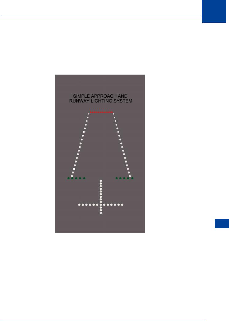
21.14 Simple Approach Lighting System. A simple approach lighting system consists of a row of lights on the extended centre line of the runway extending, whenever possible, over a distance of not less than 420 m from the threshold with a row of lights forming a crossbar 18 m or 30 m in length at a distance of 300 m from the threshold. The lights forming the crossbar shall be as nearly as practicable in a horizontal straight line at right angles to, and bisected by, the line of the centre line lights. This type of system is used on a non-instrument runway and may be used on a non-precision instrument runway.
Figure 21.1 Simple approach lighting system
Aerodrome Lighting 21
421
21 Aerodrome Lighting
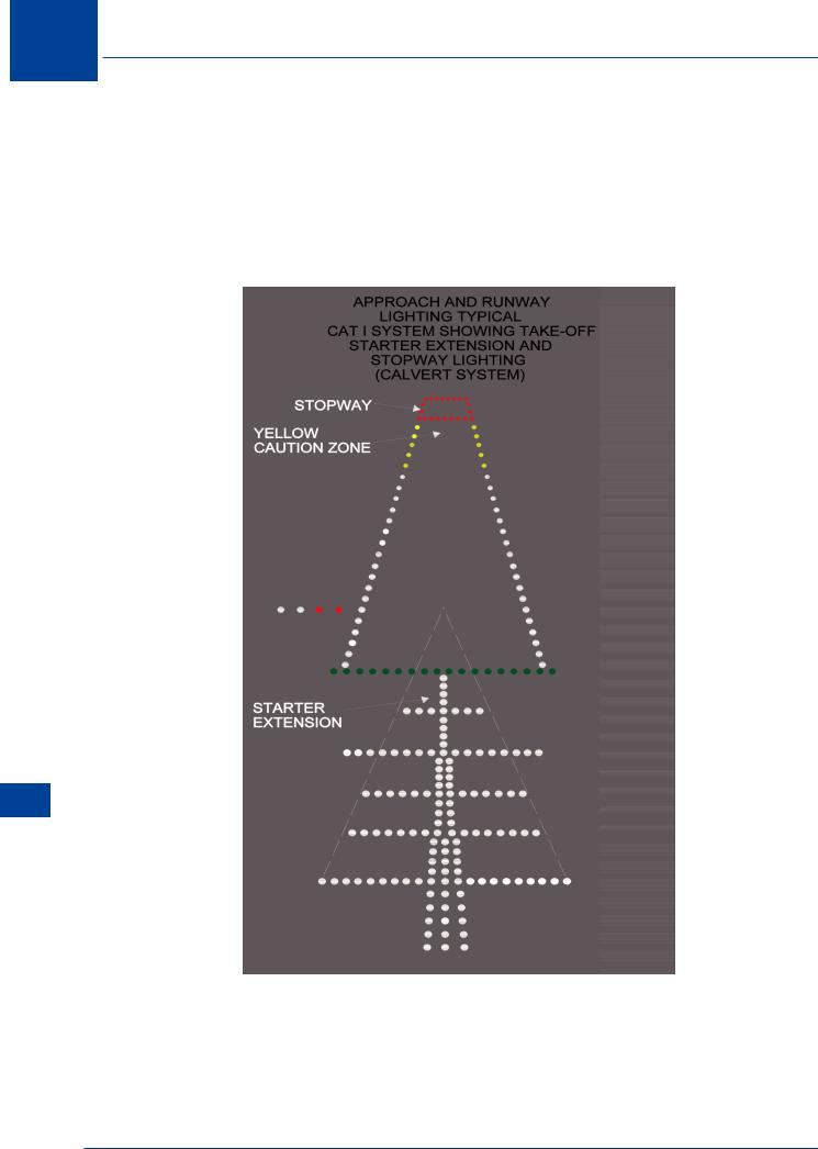
21.15 Precision Approach CAT I Lighting System. A precision approach category I lighting system consists of a row of lights on the extended centre line of the runway extending, wherever possible, over a distance of 900 m from the runway threshold. If the length is less than 900 m (which on a 3° glide path coincides with CAT I system minima - 200 ft) it is possible that an aircraft may not be over the approach lighting at DH. The 5 crossbars are 150 m apart and form three segments: the inner segment (0 - 300 m); the middle segment (300 - 600 m); and the outer segment (600 - 900 m). Any ILS or MLS azimuth antenna protruding through the plane of the lights will be treated as an obstacle and marked and lit accordingly.
Lighting Aerodrome 21
Figure 21.2 CAT I Calvert 5 bar and centre line system
422
Aerodrome Lighting 21
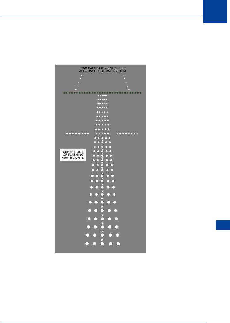
21.16 ICAO Precision Approach CAT I Lighting System. In this arrangement, the centre line is in the form of barrettes with only one crossbar at 300 m from the threshold. Again, the centre line should be 900 m in length. The centre line may be augmented with strobe lights that ‘ripple’ towards the threshold from the start of the centre line. The visibility of the threshold may be enhanced by the use of wing strobes (rotating).
Figure 21.3 ICAO CAT I approach lighting system
Aerodrome Lighting 21
423
21 Aerodrome Lighting
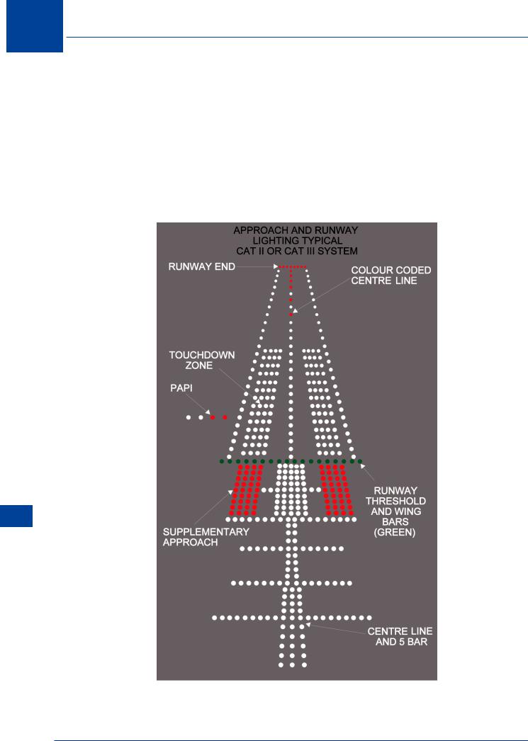
21.17 Precision Approach Category II/III Lighting System. At those aerodromes where Cat II and III approaches are conducted more complex approach lighting system are installed to enhance the possibility of the pilot achieving the visual criteria at DH to complete the landing. The systems used are various but all are based on either the Calvert 5 bar and centre line system, or the ICAO barrette system. Both systems should be 900 m long and provide some element of attitude information. In both the Calvert and the ICAO systems the inner segment (0 - 300 m from the threshold) is augmented by the supplementary approach lighting. This consists of replacing the centre line of the Calvert system with barrettes and adding red wing barrettes to both systems. The effect is to enhance the visibility and conspicuity of the inner segment. DH for Cat II is not lower than 100 ft which equates to 300 m from the threshold (assuming the pilot crosses the threshold at 50 ft).
Lighting Aerodrome 21
Figure 21.4 Approach & runway Cat II/III lighting system
424
Aerodrome Lighting 21
Figure 21.5 ICAO Cat II/III approach lighting system
Aerodrome Lighting 21
425
21 Aerodrome Lighting
© L ten Hoopen
Figure 21.6 Calvert Cat II/III system at Cork
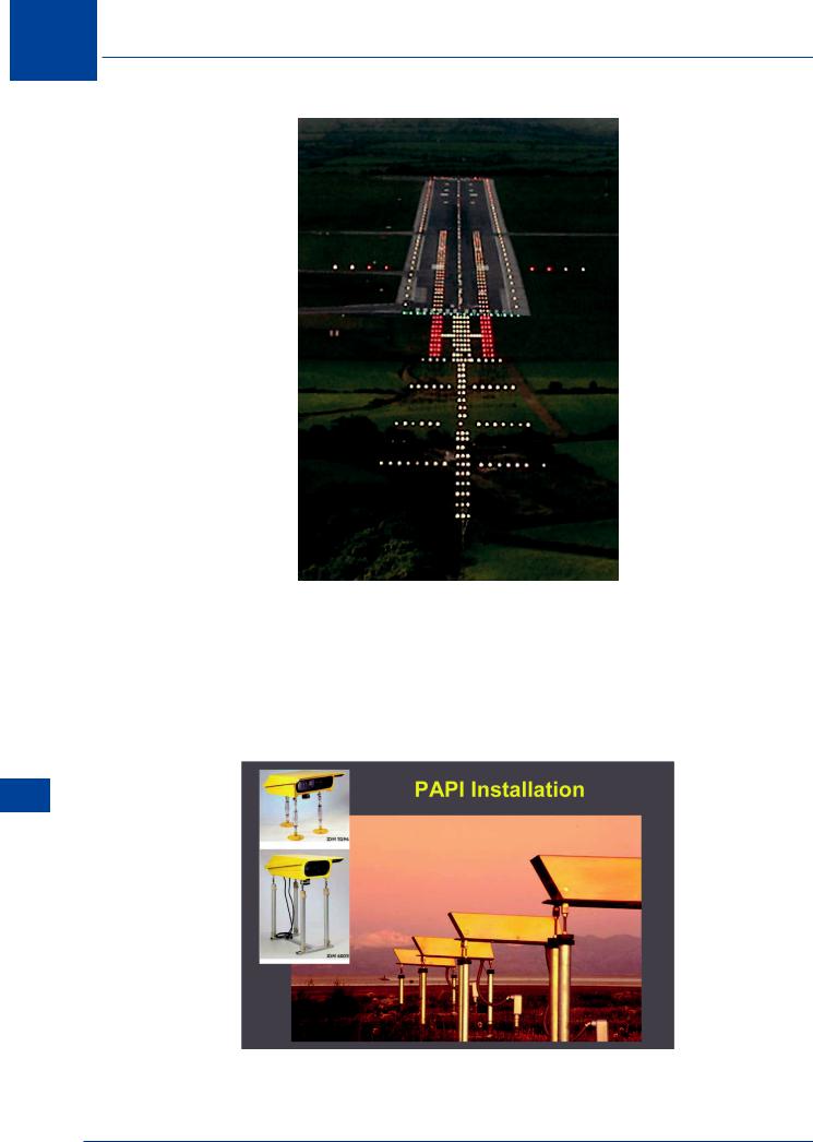
21.18 Precision Approach Path Indicators (PAPI). As an additional aid to a precision approach, glide path guidance is provided during the visual phase (after DH) by the PAPI lighting system. This consists of 4 light units showing either red or white light through precision defined angles. Each light unit is set to a different mid angle and below that angle shows red and above shows white. The overall effect is to give a reference to the median angle which is set to the required glide path (e.g. 3°). ICAO define PAPI as “A wing bar of 4 lights uniformally spaced”.
Lighting Aerodrome 21
Installation by: Godfrey Systems International, Inc
Figure 21.7 Precision approach path indicators (PAPI)
426
Aerodrome Lighting 21
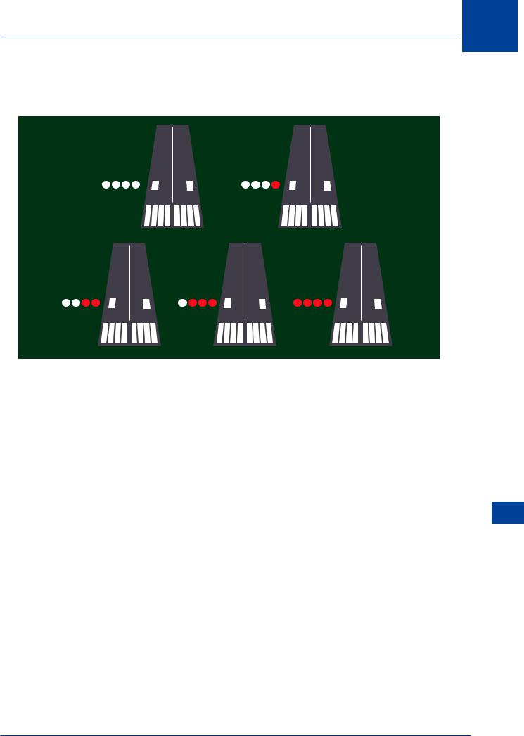
21.19 PAPI Indications. The possible combinations of the 4 light sets give 5 different indications relating to the aircraft position (correctly, the pilot’s eye) with respect to the defined glide path.
PAPIs
Well abov |
Slightly above |
On or close |
|
|
to the glide path |
Slightly belo |
Well belo |
Figure 21.8 PAPI indications
21.20 CirclingApproach. Wheretherunwayisusedforcirclingapproaches(visualmanoeuvring circling) a PAPI set is placed on either side of the runway. Normally there would only be one set on the left hand side. This allows the pilot to use the PAPI wing bars as a horizontal reference for aircraft attitude during the later part of the circling manoeuvre.
21.21 Minimum Eye Height (MEHT). If the PAPI system was located exactly at the threshold of the runway, and the pilot flew a visual approach keeping the aircraft exactly at the ‘on glide path’ position, the wheels of the aircraft would hit the ground before the aircraft reached the threshold. The distance before the threshold where the wheels hit the ground would be a function of the distance from the pilot’s eye to the bottom of the undercarriage. To overcome
this, the visual aiming point (coincident with the PAPI location) is set a distance down the |
21 |
|
|
||
runway. On code 4 instrument runways at least 2400 m in length, the aiming point is set 400 |
Lighting |
|
m from the threshold in which case, for a normal 3° glide path, the pilot’s eye would be 65 ft |
||
|
||
above the surface on crossing the threshold. This assumes that the ‘on glide path’ indication |
Aerodrome |
|
is the ‘mid angle’, when in fact it is encompassed in a bandwidth of angles within which the |
||
|
||
‘on glide path’ indication is visible. If the height of the pilot’s eye can be established when |
|
|
the aircraft is over the threshold with the lowest possible ‘on glide path’ indication, this could |
|
|
be used to determine if an aircraft can use the PAPI system as set up for that runway. The |
|
|
figure quoted on the ICAO aerodrome chart is the MEHT (minimum eye height) and is printed |
|
|
alongside the location of the PAPI on the chart. During type rating instruction, you will be |
|
|
made aware of the ‘eye to undercarriage’ requirement of the type, so that you can assess the |
|
|
usability of the PAPIs. |
|
427