


Approach Procedures |
|
8 |
|
||
|
|
|
deflection of the CDI. At some point during the final segment, a fix will be specified where glide path information can be verified.
8.27Constant Approach Slope (Stabilized Approach). Primarily for the avoidance of wake turbulence separation but also for economy and noise abatement, a procedure known as stabilized approach has been developed. The procedure requires the aircraft to depart from the IAF and descend at a constant rate throughout the procedure. Wake turbulence separation (see Chapter 16) is only applicable between approaching aircraft where the second aircraft is at the same altitude as, or within 1000 ft below, the preceding aircraft. So, by ensuring that the subsequent aircraft is always above the preceding aircraft there is no requirement for wake turbulence separation. Control of the rate of descent is achieved by aircraft attitude negating the need for power changes thus reducing noise. Also, by setting a constant power, economy in fuel usage is achieved.
8.28Missed Approach. In the event that the necessary visual criteria is not obtained at DA/H or MDA/H the final part of an instrument procedure permits a return to the IAF for another attempt or to establish the aircraft on a departure profile to go to another (alternate) aerodrome.
Obstacle Clearance Altitude/Height
8.29Obstacle Clearance Altitude/Height (OCA/H). During the development stage of the design of a procedure, the OCA/H is determined by the authority of the state through survey. This will be the altitude/height at or above which an aircraft must be flown to avoid the dominant obstacle. It will consist of the height of the obstacle plus the minimum obstacle clearance (MOC) allowance. This information will be published on the instrument procedure plate and is aircraft category dependent. OCA/H is the lowest that MDA/H can be.
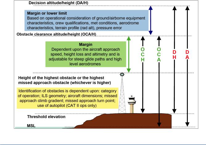
8.30DA/H for Precision Approach Procedure. This is defined as the lowest altitude or height at which a missed approach must be initiated to ensure compliance with the appropriate obstacle clearance criteria. The reference datum for a precision approach is always the threshold of the landing runway.
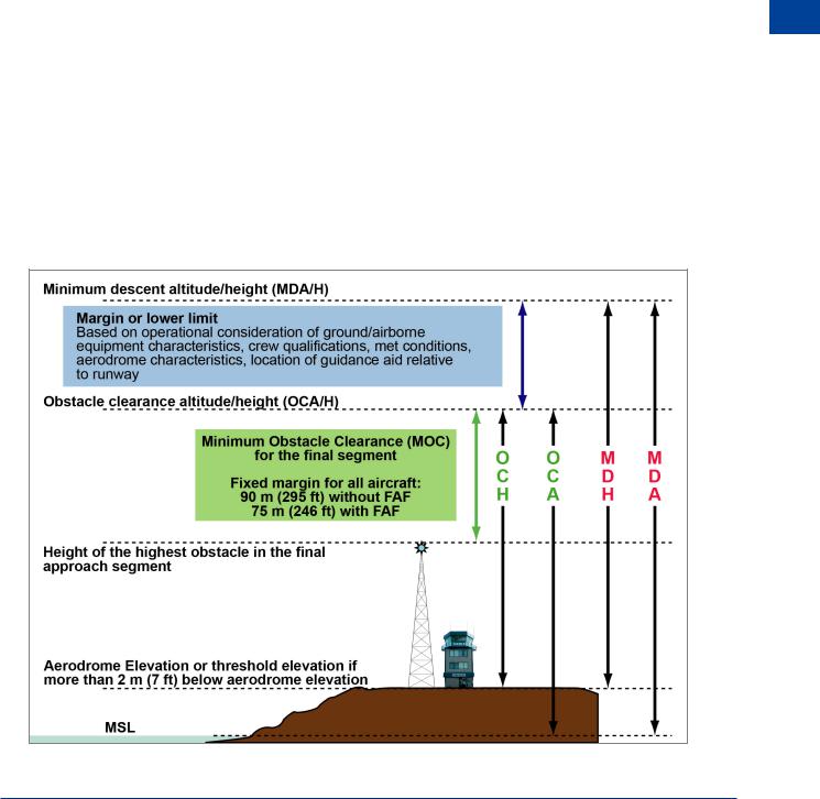
8.31OCA/H for Non-precision Approach. This is defined as the lowest altitude or height below which the aircraft cannot descend without infringing the appropriate obstacle clearance criteria. For non-precision procedures the reference datum is the aerodrome elevation or the elevation of the relevant runway threshold (if the threshold is more than 2 m (7 ft) below the aerodrome elevation).
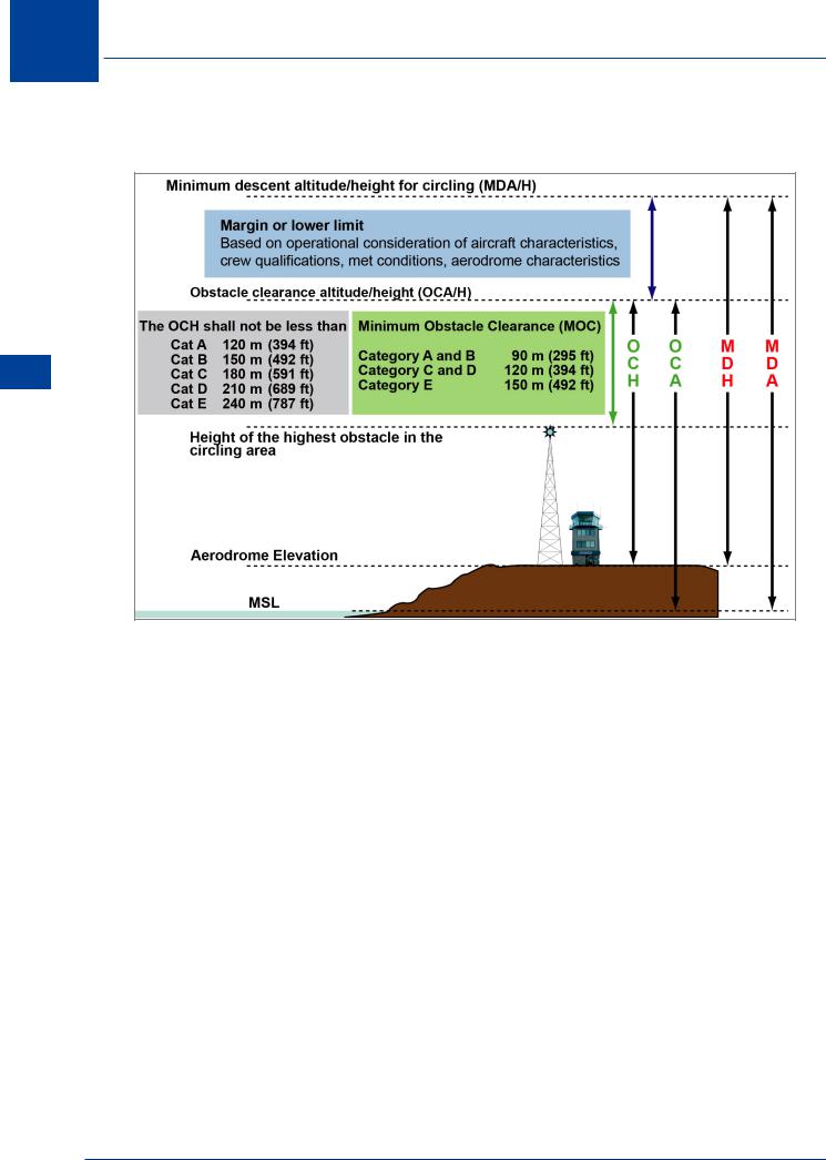
8.32OCA/H for Visual Manoeuvre (Circling) (VM(C)). This is defined as the lowest altitude or height above the aerodrome elevation, below which the aircraft cannot descend without infringing the appropriate obstacle clearance criteria. It is based on the highest obstacle in the VM(C) area with respect to the aerodrome elevation.
Operating Minima
8.33 Operating Minima. In accordance with Annex 6 and JAR-OPS 1, the operator is required to ensure that the aerodrome minima are specified for all aerodromes used in the operation. Part of this ensures that in all cases, DA/H or MDA/H is calculated taking into account the OCA/H published and the upper margin. The upper margin is specified by the operator and may be zero in which case DA/H or MDA/H would be the same as OCA/H. It takes into account data that is variable in nature i.e. the crew qualification, the OAT, anomalies in the configuration of the instrument system, the type, performance and handling characteristics of the aeroplane, the dimensions and characteristics of the runway, the visual and non-visual aids,
Approach Procedures 8
177
|
8 |
|
Approach Procedures |
|
|
||||
the obstacles on the approach,missed approach areas and climb-out areas, aircraft equipment |
|||||||||
|
|
|
|
||||||
|
|
|
|
and the means used to measure and report the meteorological conditions. |
|||||
|
|
|
|
8.34 System Minima. To ensure that the minima are realistic and give sufficient ‘buffer’ |
|||||
|
|
|
|
to allow for anomalies, for each method of conducting an instrument approach, a minimum |
|||||
|
|
|
|
height above the datum is specified below which an approach is not permitted to continue |
|||||
|
|
|
|
without the necessary visual reference. This height is known as system minima and overrides |
|||||
|
|
|
|
a lower DH or MDH. For instance, the system minimum for a CAT 1 ILS is 200 ft. If OCH plus |
|||||
|
|
|
|
the upper margin for a CAT 1 ILS approach is calculated at 170 ft, then system minimum would |
|||||
|
|
|
|
prevail and DH would be 200 ft. If on the other hand, DH is calculated at 230 ft then, as this is |
|||||
|
|
|
|
higher than system minimum, DH remains 230 ft. For Air Law, the student is only required to |
|||||
|
|
|
|
know the system minima for ILS CATs I/II/III. Note that for CAT III, DH can be zero; therefore |
|||||
|
|
|
|
system minimum for CAT III must also be zero. |
|
|
|||
8 |
|
|
|
|
|||||
|
|
|
|
|
|
|
|||
|
|
|
|
|
Category |
|
System minimum |
|
|
Approach |
|||||||||
|
|
|
|
|
|||||
|
CAT I |
|
60 m (200 ft) |
|
|||||
|
|
|
|
|
|
|
|||
Procedures |
|
|
|
|
|
||||
|
CAT II |
|
30 m (100 ft) |
|
|||||
|
|
|
|
|
|
|
|||
|
|
|
|
|
|
|
|
|
|
|
|
|
|
|
CAT III |
|
Not applicable |
|
|
|
|
|
|
|
|
|
|
|
|
Figure 8.12 ICAO system minima for ILS
8.35 Calculation of DA/H. The diagrammatic representation of the method of calculation of DA/H is shown below.
Figure 8.13 Method of determining DA/H for precision approaches
178
Approach Procedures |
|
8 |
|
||
|
|
|
8.36 Specific Data for ILS/MLS. In determining the criteria for DA/H for ILS/MLS other data needs to be taken into account and requirements specified. Wing span and the vertical distance between the wheels and the glide path (GP) aerial limitations are specified as follows:
Aircraft category |
Wing Span (m) |
Vertical distance between the |
|
wheels and the GP aerial |
|||
|
|
||
|
|
|
|
H |
30 |
3 metres |
|
|
|
|
|
A, B |
60 |
6 metres |
|
|
|
|
|
C, D |
65 |
7 metres |
|
|
|
|
|
DL |
80 |
8 metres |
|
|
Figure 8.14 |
|
Note: Category DL has been included to cater for the A380. Category H refers to Helicopters.
Other criteria for ILS include:
•CAT I is flown with pressure altimeter
•CAT II is flown with radio altimeter and flight director
•Missed approach climb gradient is 2.5%
•Glide path angle is 2.5° minimum and 3.5° maximum. CAT II/III requires 3°
8.37 Calculation of MDA/H. The diagrammatic representation of the method of calculation of MDA/H is shown below.
Figure 8.15 Method of determining MDA/MDH for non-precision approaches
Approach Procedures 8
179
8 Approach Procedures
8.38 Calculation of MDA/H for VM(C). The diagrammatic representation of the method of calculation of DA/H is shown below
Procedures Approach 8
Figure 8.16 Method of determining MDA/MDH for circling approaches
Descent Gradients
8.39Descent Gradient. The design of procedures must allow adequate space for descent from the published height crossing the facility, to the runway threshold. This is achieved by establishing a maximum allowable descent gradient for each segment of the procedure with the most critical being the final segment where threshold speed (or the ability to decelerate to it) will be a function of gradient. The optimum descent gradient in the final approach should not exceed 5.2% (50 m/km; approx 300 ft/NM) which is equivalent to a 3° glide path. Where a steeper gradient is necessary the maximum permissible is 6.5% (65 m/km (400 ft/NM) which is equivalent to a 3.8° glide path). In the case of a precision approach the operationally preferred glide path angle is 3° and this is mandatory for CAT II/III. An ILS GP in excess of 3° is used only where an alternative means of satisfying obstacle clearance requirements is impractical.
8.40High Rate Descents. Gradients over 6.5% may result in descent rates exceeding the recommended maximum rate of descent for some aircraft. Pilots flying such approaches should be aware of this before starting the approach. High rate descents are not permitted as a means of avoiding noise abatement procedures. Where GPs greater than 6.5% are established (e.g. 9.5% /5.5° at London City), the authority of the state in which the aerodrome is situated must give specific approval; the operator must be approved to carry out high rate descents; specially approved aircraft must be used and pilots specially trained.
180