

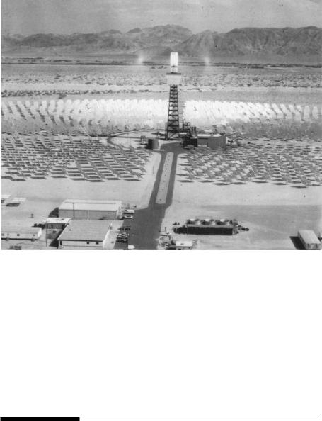
FIGURE 9-3
Solar II plant site view. (Source: U.S. Department of Energy.)
the Sandia laboratory for this plant is sodium and potassium nitrate which works as a single phase liquid, and is colorless and odorless. In addition to having the needed thermal properties up to the operating temperature of 1,050°F, it is inexpensive and safe.
Tables 9-2 and 9-3 give the technical design features of the experimental Solar II power plant. The operating experience to date indicates the overall plant capacity factor of 20 percent, and the overall thermal to electrical conversion efficiency of 16 percent. It is estimated that 23 percent overall efficiency can be achieved in a commercial plant design using this technology.
9.3Synchronous Generator
The electromechanical energy conversion in the solar thermal power system is accomplished by the synchronous machine, which runs at a constant speed to produce 60 Hz electricity. This power is then directly used to meet the local loads, and/or to feed the utility grid lines.
The electromagnetic features of the synchronous machine are shown in Figure 9-5. The stator is made of conductors placed in slots of magnetic iron
© 1999 by CRC Press LLC
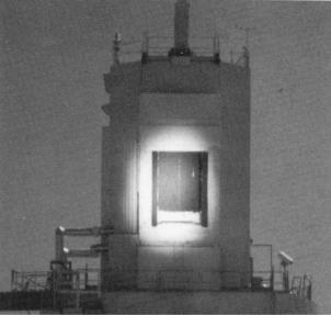
FIGURE 9-4
Experimental 1,050°F thermal receiver tower for Solar II power plant. (Source: DOE/Sandia National Laboratory.)
laminations. The stator conductors are connected in three phase coils. The rotor consists of magnetic poles created by the field coils carrying direct current. The rotor is driven by steam turbine to create a rotating magnetic field. Because of this rotation, the rotor field coils use slip rings and carbon brushes to supply DC power from a stationary source.
The stator conductors are wound in three groups, connected in three-phase configuration. Under the rotating magnetic field of the rotor, the three phase coils generate AC voltages that are 120 electrical degrees out of phase with each other. If the electromagnetic structure of the machine has p pole pairs, and it is required to generate electricity at frequency f, then the rotor must rotate at N revolution per minute given by the following:
N = 60 |
f |
(9-2) |
|
p |
|||
|
|
The synchronous machine must operate at this constant speed to generate power at the specified frequency. In a stand-alone solar thermal system, small speed variations could be tolerated within the frequency tolerance band of the AC system. If the generator is connected to the grid, it must be synchronous with the grid frequency, and must operate exactly at the grid frequency at all times. Once synchronized, such a machine has inherent tendency to remain
© 1999 by CRC Press LLC

TABLE 9-2
Solar II Design Features
Site
•Mojave Desert in California
•1,949 feet above sea level
•7.5 kWh/m2-day annual average daily insolation
•95 acres of land
Tower
•Reused from Solar I plant
•277 feet to top of the receiver
•211 feet to top of BCS deck
Heliostats
•1,818 Solar I heliostats, 39.1 m2,
91 percent reflectivity
•108 new Lug heliostats, 95.1 m2,
93 percent reflectivity
•81,000 m2 total reflective surface
•Can operate in winds up to 35 mph
Receiver
•New for Solar II plant
•Supplier Rockwell
•42.2 MW thermal power rating
•Average flux 429 suns (429 kW/m2)
•Peak flux 800 suns
•24 panels, 32 tubes per panel
•20 feet tall and 16.6 feet diameter
•0.8125 inch tube OD
•0.049 inch tube wall thickness
•Tubes 316H stainless steel
Thermal Storage System
•Supplier Pitt Des Moines
•Two new 231,000 gallon storage tanks, 38 ft ID
•Cold tank carbon steel, 25.8 ft high, 9 inch insulation
•Hot tank 304 stainless steel, 27.5 ft high,
18 inches insulation
• 3 hours of storage at rated turbine output
Nitrate salt — Chilean Nitrate
•60% NaNO3, 40% KNO3
•Melting temperature 430°F
•Decomposing temperature 1,100°F
•Energy storage density two thirds of water
•Density two times that of water
•Salt inventory 3.3 million pounds
Steam Generator
•Supplier ABB Lummus
•New salt-in-shell superheater
•New slat-in-tube kettle boiler
•New salt-in-shell preheater
Turbine-Generator
•Supplier General Electric Company
•Refurbished from Solar I plant
•10 MWe net
•12 MWe gross
(Source: U.S. Department of Energy and Southern California Edison Company.2)
TABLE 9-3
Solar II Operating Features
Thermodynamic Cycle |
Electrical Power Generator |
|
|
Hot salt temperature 1,050°F |
Capacity 10 MWe |
Cold salt temperature 550°F |
Capacity factor 20% |
Steam temperature 1,000°F |
Overall solar-electric efficiency 16% |
Steam pressure 1,450 psi |
Cost of conversion from Solar I $40 M |
Receiver salt flow rate 800,000 lbs/hour |
|
Steam generator flow rate 660,000 lbs/hour |
|
(Source: U.S. Department of Energy and Southern California Edison Company.)
© 1999 by CRC Press LLC

FIGURE 9-5
Cross section view of the synchronous generator.
in synchronism. However, a large sudden disturbance such as a step load can force the machine out of the synchronism, as discussed in Section 9.3.4.
9.3.1Equivalent Electrical Circuit
The equivalent electricity circuit of the synchronous machine can be represented by a source of alternating voltage E and an internal series resistance Rs and reactance Xs representing the stator winding. The resistance, being much smaller than the reactance, can be ignored to reduce the equivalent circuit to a simple form shown in Figure 9-6. If the machine is supplying the load current I lagging the terminal voltage V by phase angle φ, it must internally generate the voltage E, which is the phasor sum of the terminal voltage and the internal voltage drop IXs. The phase angle between the V and E is called the power angle δ. At zero power output, load current is zero and so is the IXs vector, making V and E in phase having zero power angle. Physically, the power angle represents the angle by which the rotor position lags the stator-induced rotating magnetic field. The output power can be
© 1999 by CRC Press LLC