

6
Electrical Generator
6.1Electromechanical Energy Conversion
The conversion of the mechanical power of the wind turbine into the electrical power can be accomplished by any one of the following types of the electrical machines:
•the direct current (DC) machine.
•the synchronous machine.
•the induction machine.
These machines work on the principles of the electromagnetic actions and reactions. The resulting electromechanical energy conversion is reversible. The same machine can be used as the motor for converting the electrical power into mechanical power, or as the generator converting the mechanical power into the electrical power.
Figure 6-1 depicts common features of the electrical machines. Typically, there is an outer stationary member (stator) and an inner rotating member (rotor). The rotor is mounted on bearings fixed to the stator. Both the stator and the rotor carry cylindrical iron cores, which are separated by an air gap. The cores are made of magnetic iron of high permeability, and have conductors embedded in slots distributed on the core surface. Alternatively, the conductors are wrapped in the coil form around salient magnetic poles. Figure 6-2 is the cross-sectional view of the rotating electrical machine with the stator with salient poles and the rotor with distributed conductors. The magnetic flux, created by the excitation current in one of the two members, passes from one core to the other in the combined magnetic circuit always forming a closed loop. The electromechanical energy conversion is accomplished by interaction of the magnetic flux produced by one member with the electric current in the other member. The latter may be externally supplied or electromagnetically induced. The induced current is proportional to the rate of change in the flux linkage due to rotation.
© 1999 by CRC Press LLC
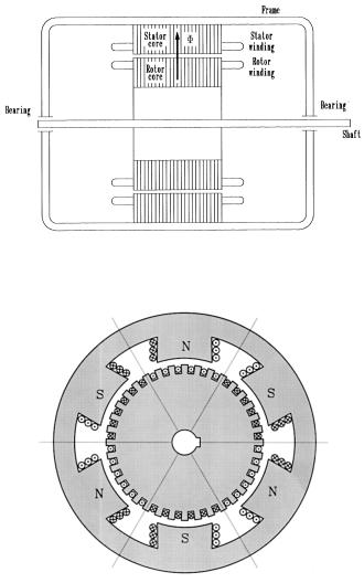
FIGURE 6-1
Common constructional features of the rotating electrical machines.
FIGURE 6-2
Cross section of the electrical machine stator and rotor.
The various types of machines differ fundamentally in the distribution of the conductors forming the windings, and in whether the elements have continuous slotted cores or salient poles. The electrical operation of any given machine depends on the nature of the voltages applied to its windings. The narrow annular air gap between the stator and the rotor is the critical region of the machine operation, and the theory of performance is mainly concerned with the conditions in or near the air gap.
© 1999 by CRC Press LLC
6.1.1DC Machine
All machines are internally alternating current (AC) machines because of the conductor rotation in the magnetic flux of alternate north and south polarity. The DC machine must convert the AC into DC, and does so by using the mechanical commutator. The commutator performs this function by sliding carbon brushes on a series of copper segments. The positive output terminal is, thus, continuously switched to the conductor generating the positive polarity voltage, as is the negative polarity terminal. The sliding contacts inherently result in low reliability and high maintenance cost. Despite this disadvantage, the DC machine had been used extensively until early 1980s because of its extremely easy speed control. It has been used in a limited number of wind power installations of small capacity, particularly where electricity can be locally used in the DC form. However, the conventional DC machine with mechanical commutator has fallen out of favor.
The conventional DC machine is either self-excited by shunt or series coils carrying DC current to produce a magnetic field. The DC machine of the present day is often designed with permanent magnets to eliminate the field current requirement, hence, the commutator. It is designed in the “insideout” configuration. The rotor carries the permanent magnet poles and the stator carries the wound armature which produces AC current. The AC is then rectified using the solid state rectifiers. Such machines do not need the commutator and the brushes, hence, the reliability is greatly improved. The permanent magnet DC machine is used with small wind turbines, however, due to limitation of the permanent magnet capacity and strength. The brushless DC machine is expected to be limited to ratings below one hundred kW.
6.1.2Synchronous Machine
Most of the electrical power consumed in the world is generated by the synchronous generator. For this reason, the synchronous machine is an established machine. The machine works at a constant speed related to the fixed frequency. Therefore, it is not well suited for variable-speed operation in the wind plants. Moreover, the synchronous machine requires DC current to excite the rotor field, which needs sliding carbon brushes on slip rings on the rotor shaft. This poses a limitation on its use. The need of the DC field current and the brushes can be eliminated by using the reluctance rotor, where the synchronous operation is achieved by the reluctance torque. The reliability is greatly improved while reducing the cost. The machine rating, however, is limited to tens of kW. The reluctance synchronous generator is being investigated at present for small wind generators.1
The synchronous machine is ideally suited in constant-speed systems, such as in the solar thermal power plants. The machine is, therefore, covered in some detail in Chapter 9.
© 1999 by CRC Press LLC