- •Preface
- •About the Author
- •About the Book
- •Acknowledgment
- •Contents
- •1.1 Industry Overview
- •1.2 Incentives for Renewables
- •1.3 Utility Perspective
- •1.3.1 Modularity
- •1.3.2 Emission-Free
- •References
- •2.1 Wind in the World
- •2.3 Europe
- •2.4 India
- •2.5 Mexico
- •2.6 Ongoing Research and Development
- •References
- •3.1 Present Status
- •3.2 Building Integrated pv Systems
- •3.3 pv Cell Technologies
- •3.3.2 Polycrystalline and Semicrystalline
- •3.3.3 Thin Films
- •3.3.4 Amorphous Silicon
- •3.3.5 Spheral
- •3.3.6 Concentrated Cells
- •3.4 pv Energy Maps
- •References
- •5.1 System Components
- •5.1.1 Tower
- •5.1.2 Turbine Blades
- •5.1.3 Yaw Control
- •5.1.4 Speed Control
- •5.2 Turbine Rating
- •5.3 Electrical Load Matching
- •5.5 System Design Features
- •5.5.1 Number of Blades
- •5.5.2 Rotor Upwind or Downwind
- •5.5.3 Horizontal Axis Versus Vertical Axis
- •5.5.4 Spacing of the Towers
- •5.6 Maximum Power Operation
- •5.6.2 Peak Power Tracking Scheme
- •5.7 System Control Requirements
- •5.7.1 Speed Control
- •5.7.2 Rate Control
- •5.8 Environmental Aspects
- •5.8.1 Audible Noise
- •5.8.2 Electromagnetic Interference (EMI)
- •References
- •6.1 Electromechanical Energy Conversion
- •6.1.1 DC Machine
- •6.1.2 Synchronous Machine
- •6.1.3 Induction Machine
- •6.2 Induction Generator
- •6.2.1 Construction
- •6.2.2 Working Principle
- •6.2.3 Rotor Speed and Slip
- •6.2.4 Equivalent Circuit for Performance Calculations
- •6.2.8 Transients
- •References
- •7.1 Speed Control Regions
- •7.2 Generator Drives
- •7.3 Drive Selection
- •References
- •8.1 The pv Cell
- •8.2 Module and Array
- •8.3 Equivalent Electrical Circuit
- •8.4 Open Circuit Voltage and Short Circuit Current
- •8.6 Array Design
- •8.6.1 Sun Intensity
- •8.6.2 Sun Angle
- •8.6.3 Shadow Effect
- •8.6.4 Temperature Effect
- •8.6.5 Effect of Climate
- •8.6.6 Electrical Load Matching
- •8.6.7 Sun Tracking
- •8.7 Peak Power Point Operation
- •8.8 pv System Components
- •References
- •9.1 Energy Collection
- •9.1.1 Parabolic Trough
- •9.1.2 Central Receiver
- •9.1.3 Parabolic Dish
- •9.2 Solar II Power Plant
- •9.3 Synchronous Generator
- •9.3.1 Equivalent Electrical Circuit
- •9.3.2 Excitation Methods
- •9.3.3 Electrical Power Output
- •9.3.4 Transient Stability Limit
- •9.4 Commercial Power Plants

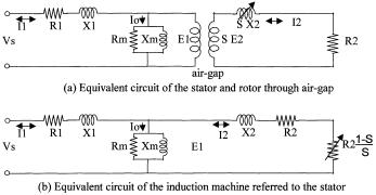
FIGURE 6-6
Equivalent electrical circuit of induction machine for performance calculations.
Under the steady state operation at slip “s”, the induction generator has the following operating speeds:
• |
stator flux wave speed |
Ns |
|
• |
rotor mechanical speed |
Nr = (1 – s) · Ns |
|
• |
stator flux speed with respect to rotor |
s · Ns |
|
• |
rotor flux speed with respect to stator |
Nr + s · Ns = Ns |
(6-5) |
6.2.4Equivalent Circuit for Performance Calculations
The theory of operation of the induction machine is represented by the equivalent circuit shown in Figure 6-6. It is similar to that of the transformer. The left-hand side of the circuit represents the stator and the right hand side, the rotor. The stator and the rotor currents are represented by I1 and I2 , respectively. The vertical circuit branch at the junction carries the magnetizing (or excitation) current Io, which sets the magnetic flux required for the electromagnetic operation of the machine. The total stator current is then the sum of the rotor current and the excitation current. The air-gap separation is not shown, nor is the difference in the number of turns in the stator and rotor windings. This essentially means that the rotor is assumed to have the same number of turns as the stator and has an ideal 100 percent magnetic coupling. We calculate the performance parameters taking the stator winding as the reference. The actual rotor voltage and current would be related with the calculated values through the turn ratio between the two windings. Thus, the calculations are customarily performed in terms of the stator, as we shall do in this chapter. This matches the practice, as the performance measurements are always done on the stator side. The rotor is inaccessible for any routine measurements.
© 1999 by CRC Press LLC

Most of the flux links both the stator and the rotor. The flux which does not link both is called the leakage flux. The leakage flux is represented by the leakage reactance. One-half of the total leakage reactance is attributed to each side, namely the stator leakage reactance X1 and the rotor leakage reactance X2 in Figure 6-6(b). The stator and the rotor conductor resistance are represented by R1 and R2, respectively. The magnetizing parameters Xm and Rm represent the permeability and losses (hysteresis and eddy current) in the magnetic circuit of the machine.
The slip dependent rotor resistance R2 · (1-s)/s represents the electromechanical power conversion. The power conversion per phase of the threephase machine is given by I22 R2 · (1 –s)/s. The three-phase power conversion is then as follows:
P |
= 3 I 2 |
R |
2 |
(1− s) s watts. |
(6-6) |
em |
2 |
|
|
|
The machine capacity rating is the power developed under rated conditions, that is as follows:
Machine Rating = |
Pem rated |
kW or |
Pem rated |
horsepower. |
(6-7) |
|
746 |
||||
1000 |
|
|
|
||
The electromechanical power conversion given by Equation 6-6 is physically appreciated as follows. If the machine is not loaded and has zero friction, it runs at the synchronous speed, the slip is zero and the value of R2(1–s)/s becomes infinite. The rotor current is then zero, and so is Pem , as it should be. When the rotor is standing still, the slip is unity and the value of R2 · (1–s)/s is zero. The rotor current is not zero, but the Pem is zero, as the mechanical power delivered by the standstill rotor is zero.
At any slip other than zero or unity, neither the rotor current nor the speed is zero, resulting in a non-zero value of Pem .
The mechanical torque is given by the power divided by the angular speed, that is as follows:
Tem = Pem |
ω |
(6-8) |
where Tem = electromechanical torque |
developed in the |
rotor in new- |
ton-meters |
|
|
ω= angular speed of the rotor = 2π.Ns · (1–s)/60 in mechanical radians/sec.
Combining the above equations, we obtain the torque at any slip s, as follows:
T |
= (180 2πN |
).I2 |
R |
2 |
s Newton-meters |
(6-9) |
em |
s |
2 |
|
|
|
The value of 12 in equation (6-9) is determined by the equivalent circuit parameters, and is slip dependent. The torque developed by the induction
© 1999 by CRC Press LLC

machine rotor is, therefore, highly slip-dependent, as is discussed later in this chapter.
We take a note here that the performance of the induction machine is completely determined by the equivalent circuit parameters. The circuit parameters are supplied by the machine manufacturer, but can be determined by two basic tests on the machine. The full-speed test under no load and the zero-speed test with blocked rotor determine the complete equivalent circuit of the machine.2-3
The equivalent circuit parameters are generally expressed in perunit of their respective rated values per phase. The rated impedance per phase is defined as the following:
= Rated voltage per phase
Z ohms. (6-10)
rated |
Rated current per phase |
|
For example, the perunit (pu) stator resistance is expressed as the following:
R1 perunit = |
R1 in ohms |
(6-11) |
Z in ohms |
||
|
rated |
|
and similar expressions for all other circuit parameters. When expressed as such, X1 and X2 are equal, each a few to several percent. The R1 and R2 are approximately equal, each a few percent of the rated impedance. The magnetizing parameters Xm and Rm are usually large, in several hundred percent of Zrated, hence, drawing negligible current compared to the rated current. For this reason, the magnetizing branch of the circuit is often ignored in making approximations of the machine performance calculations.
All of the above performance equations hold true for both the induction motor and the induction generator by taking the proper sign of the slip. In the generator mode, the value of the slip is negative in the performance equations wherever it appears. We must also remember that the real power output is negative, that is the shaft receives power instead of delivering it. The reactive power drawn from the stator terminals remains lagging with respect to the line voltage, hence, we say that the induction generator delivers leading reactive power. Both of these mean that the magnetizing volt-amperes are supplied by an external source.
6.2.5Efficiency and Cooling
The values of R1 and R2 in the equivalent circuit represent electrical losses in the stator and the rotor, respectively. As will be seen later, for a welldesigned machine, the magnetic core loss must equal the conductor loss. Therefore, with R1 and R2 expressed in perunit of the base impedance, the induction machine efficiency is approximately equal to the following:
© 1999 by CRC Press LLC

η = 1− 2 (R1 + R2 ) |
(6-12) |
For example, a machine with R1 and R2 each 2 percent, we write R1 = R2 = 0.02 perunit. The efficiency is then simply 1–2(0.02+0.02) = 0.92 perunit, or 92 percent. Eight percent of the input power in this machine is lost in the conversion process.
The losses generated in the machine are removed by providing adequate cooling. Small machines are generally air-cooled. Large generators located inside the nacelle can be difficult to cool by air. Water cooling, being much more effective than air-cooling, can be advantageous in three ways:
•for the same machine rating, the water cooling reduces the generator weight on the nacelle, thus benefiting the structural design of the tower.
•it absorbs and thus reduces the noise and vibrations.
•it eliminates the nacelle opening by mounting the weather-air heat exchanger outside, making the nacelle more weather-proof.
•overall, it reduces the maintenance requirement, a significant benefit in large machines usually sitting on tall towers.
6.2.6Self-Excitation Capacitance
As the generator, the induction machine has one drawback of requiring reactive power for excitation. The exciting power can be provided by an external capacitor connected to the generator terminals (Figure 6-7). No separate AC supply is needed in this case. In the grid-connected generator, the reactive power is supplied from the synchronous generators working at the other end of the grid. Where the grid capacity of supplying the reactive power is limited, local capacitors can be used to partly supply the needed reactive power.
The induction generator will self-excite using the external capacitor only if the rotor has an adequate remnant magnetic field. In the self-excited mode, the generator output frequency and voltage are affected by the speed, the
FIGURE 6-7
Self-excited induction generator with external capacitor.
© 1999 by CRC Press LLC

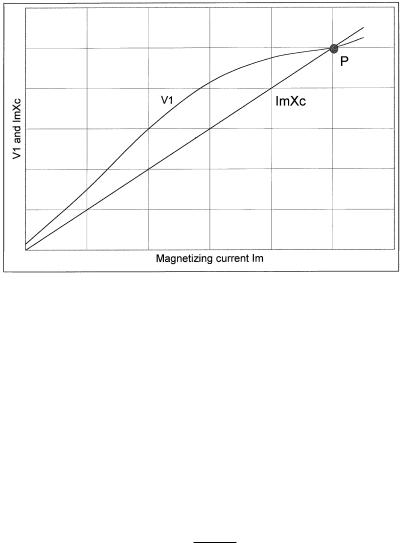
FIGURE 6-8
Determination of stable operation of self-excited induction generator.
load, and the capacitance value in farads. The operating voltage and frequency are determined below in terms of the approximate equivalent circuit of Figure 6-7.
On no load, the capacitor current Ic = V1/Xc must be equal to the magnetizing current Im = V1/Xm . The voltage V1 is a function of Im , linearly rising until the saturation point of the magnetic core is reached (Figure 6-8). The stable operation requires the line ImXc to intersect the V1 versus Im curve. The operating point is fixed where V1/Xc equal V1/Xm , that is when 1/Xc = 1/Xm , where Xc = 1/ωC. This settles the operating frequency in hertz. With the capacitor value C, the output frequency of the self-excited generator is therefore:
f = |
1 |
(6-13) |
2πCXm |
Under load conditions, the generated power V1I2 cosφ2 provides for the power in the load resistance R and the loss in Rm. The reactive currents must sum to zero, i.e.:
V1 |
+ |
V1 |
+ I2 |
sin φ2 |
= |
V1 |
(6-14) |
|
|
Xc |
|||||
X Xm |
|
|
|
|
|||
Equation 6-14 determines the output voltage of the machine under load.
© 1999 by CRC Press LLC

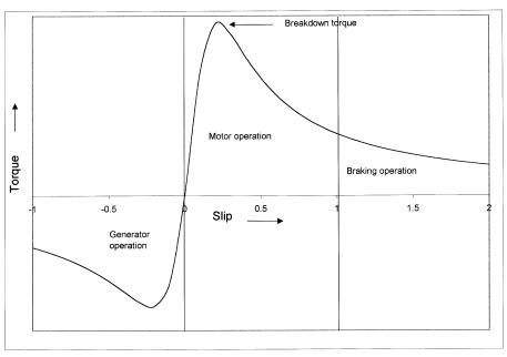
FIGURE 6-9
Torque versus speed characteristic of the induction machine in three operating modes.
The Equations 6-13 and 6-14 determine the induction generator output frequency and voltage with a given value of the capacitance. Inversely, they can be used to determine the required value of the capacitance for the desired frequency and the voltage.
6.2.7Torque-Speed Characteristic
If we vary the slip over a wide range in the equivalent circuit, we get the torque-speed characteristic as shown in Figure 6-9. In the region of negative slip, the machine works as the generator powering the electrical load connected to its terminals. In the region of positive slip, it works as the motor turning the mechanical load connected to its shaft. In addition to the motoring and the generating regions, the induction machine has yet a third operating mode, and that is the braking mode. If the machine is operated at slips >1 by turning it backward, it absorbs power without putting anything out. That is, it works as a brake. The power in this case is converted into 12R loss in the rotor conductors, which must be dissipated as heat. The eddy current brake works on this principle. As such, in case of emergencies, the grid-connected induction generator can be used as brake by reversing the three-phase voltage sequence at the stator terminals. This reverses the direction
© 1999 by CRC Press LLC
