

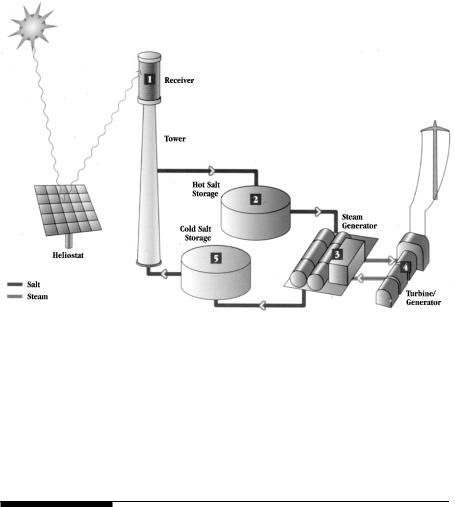
FIGURE 9-1
Solar thermal power plant schematic for generating electricity.
A major benefit of this scheme is that it incorporates the thermal energy storage for duration in hours with no degradation in performance, or longer with some degradation. This feature makes the technology capable of producing high-value electricity for meeting peak demands. Moreover, compared to the solar photovoltaic, the solar thermal system is economical, as it eliminates the costly semiconductor cells.
9.1Energy Collection
The solar thermal energy is collected by concentrators. Three alternative configurations of the concentrators are shown in Figure 9-2. Their main features and applications are as follows:
9.1.1Parabolic Trough
The parabolic trough system is by far the most commercially matured of the three technologies. It focuses the sunlight on a glass-encapsulated tube running along the focal line of the collector. The tube carries heat absorbing liquid, usually oil, which in turn, heats water to generate steam. More than 350 MW of parabolic trough capacity is operating in the California Mojave
© 1999 by CRC Press LLC
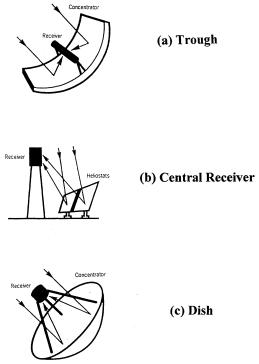
FIGURE 9-2
Alternative thermal energy collection technologies.
Desert and is connected to the Southern California Edison’s utility grid. This is more than 90 percent of the world’s solar thermal capacity at present.
9.1.2Central Receiver
In the central receiver system, an array of field mirrors focus the sunlight on the central receiver mounted on a tower. To focus the sun on the central receiver at all times, each heliostat is mounted on the dual-axis suntracker to seek position in the sky that is midway between the receiver and the sun. Compared to the parabolic trough, this technology produces higher concentration, and hence, higher temperature working medium, usually a salt. Consequently, it yields higher Carnot efficiency, and is well suited for utility scale power plants in tens or hundreds of megawatt capacity.
9.1.3Parabolic Dish
The parabolic dish tracks the sun to focus heat, which drives a sterling heat engine-generator unit. This technology has applications in relatively small capacity (tens of kW) due the size of available engines and wind loads on
© 1999 by CRC Press LLC