

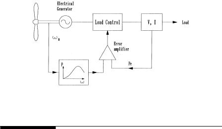
FIGURE 5-15
Maximum power operation using power control scheme.
5.7System Control Requirements
5.7.1Speed Control
The rotor speed must be controlled for three reasons:
•to capture more energy, as seen above.
•to protect the rotor, the generator and the power electronic equipment from overloading at high wind.
•when the generator is disconnected accidentally or for a scheduled event, losing the electrical load. Under this condition, the rotor speed may run away, destroying it mechanically, if it is not controlled.
The speed control requirement of the rotor has five separate regions (Figure 5-16):
1.The cut-in speed at which the turbine starts producing power. Below this speed, it is not efficient to turn on the turbine.
2.The constant maximum Cp region where the rotor speed varies with the wind-speed variation to operate at the constant TSR corresponding to the maximum Cp value.
3.During high winds, the rotor speed is limited to an upper constant limit based on the design limit of the system components. In the
constant speed region, the Cp is lower than the maximum Cp, and the power increases at a lower rate than that in the first region.
4.At still higher wind speeds, such as during a gust, the machine is operated at constant power to protect the generator and the power
©1999 by CRC Press LLC
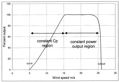
FIGURE 5-16
Five regions of the turbine speed control.
electronics from overloading. This can be achieved by lowering the rotor speed. If the speed is decreased by increasing electrical load, the generator will be overloaded, defeating the purpose. To avoid the generator overloading, some sort of brake, eddy current, or other type, must be installed on the rotor.
5.The cutout speed. Beyond certain wind speed, the rotor is shut off producing power in order to protect the blades, the electrical generator, and other components of the systems.
5.7.2Rate Control
The large rotor inertia of the blades must be taken into account in controlling the speed. The acceleration and deceleration must be controlled to limit the dynamic mechanical stress on the rotor blades and the hub, and the electrical load on the generator and the power electronics. The instantaneous difference between the mechanical power produced by the blades and the electrical power delivered by the generator will change the rotor speed as follows:
J |
dω |
= |
Pm − Pe |
(5-4) |
|
ω |
|||
|
dt |
|
||
where J = polar moment of inertia of the rotor ω = angular speed of the rotor
Pm = mechanical power produced by the blades Pe = electrical power delivered by the generator.
© 1999 by CRC Press LLC