

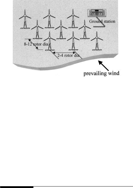
FIGURE 5-12
Optimum tower spacing in wind farms in flat terrain.
•larger turbines cost less per MW capacity and occupy less land area.
•fewer large machines can reduce the MWh energy crop per year, as downtime of one machine would have larger impact on the energy output.
•the wind power fluctuations and electrical transients on fewer large machines would cost more in electrical filtering of the power and voltage fluctuations, or would degrade the quality of power, inviting penalty from the grid.
The optimization method presented by Roy2 takes into account the above trades. Additionally, it includes the effect of tower height that goes with the turbine diameter, the available standard ratings, cost at the time of procurement, and the wind speed. The wake interaction and tower shadow are ignored for simplicity.
Such optimization leads to a site specific number and size of the wind turbines that will minimize the energy cost.
5.6Maximum Power Operation
As seen earlier, operating the wind turbine at a constant tip-speed ratio corresponding to the maximum power point at all times can generate 20 to 30 percent more electricity per year. However, this requires a control scheme
© 1999 by CRC Press LLC
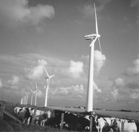
FIGURE 5-13
Original land use continues in a wind farm in Germany. (Source: Vestas Wind Systems, Denmark With permission.)
to operate with variable speed. Two possible schemes used with the variablespeed operation are as follows:
5.6.1Constant Tip-Speed Ratio Scheme
This scheme is based on the fact that the maximum energy is extracted when the optimum tip-speed ratio is maintained constantly at all wind speeds. The optimum TSR is a characteristic of the given wind turbine. This optimum value is stored as the reference TSR in the control computer. The wind speed is continuously measured and compared with the blade tip speed. The error signal is then fed to the control system, which changes the turbine speed to minimize the error (Figure 5-14). At this time the rotor must be operating at the reference TSR generating the maximum power. This scheme has a disadvantage of requiring the local wind speed measurements, which could
© 1999 by CRC Press LLC
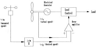
FIGURE 5-14
Maximum power operation using rotor tip-speed control scheme.
have significant error particularly in a large wind farm with shadow effects. Being sensitive to the changes in the blade surface, the optimum TSR gradually changes. The computer reference TSR must be changed accordingly many times over the life. This is expensive. Besides, it is difficult to determine the new optimum tip-speed ratio with changes that are not fully understood, nor easily measured.
5.6.2Peak Power Tracking Scheme
The power versus speed curve has a single well-defined peak. If we operate at the peak point, a small increase or decrease in the turbine speed would result in no change in the power output, as the peak point locally lies in a flat neighborhood. Therefore, a necessary condition for the speed to be at the maximum power point is as follows:
dP |
= 0 |
(5-3) |
|
dω |
|||
|
|
This principle is used in the control scheme (Figure 5-15). The speed is increased or decreased in small increments, the power is continuously measured, and ∆P/∆ω is continuously evaluated. If this ratio is positive, meaning we get more power by increasing the speed, the speed is further increased. On the other hand, if the ratio is negative, the power generation will reduce if we change the speed any further. The speed is maintained at the level where ∆P/∆ω is close to zero. This method is insensitive to the errors in local wind speed measurement, and also to the wind turbine design. It is, therefore, the preferred method. In a multiple machine wind farm, each turbine must be controlled by its own control loop with operational and safety functions incorporated.
© 1999 by CRC Press LLC