


Unlike the induction machine covered later in this chapter, the synchronous machine, when used in the grid-connected system, has some advantage. It does not require the reactive power from the grid. This results in a better quality of power at the grid interface. This advantage is more pronounced when the wind farm is connected to a small capacity grid using long low voltage lines. For this reason, early California plants used synchronous generators. Today’s wind plants generally connect to larger grids using shorter lines, and almost universally use the induction generator.
6.1.3Induction Machine
Most of the electrical power in the industry is consumed by the induction machine driving the mechanical load. For this reason, the induction machine represents a well established technology. The primary advantage of the induction machine is the rugged brushless construction and no need for separate DC field power. The disadvantages of both the DC machine and the synchronous machine are eliminated in the induction machine, resulting in low capital cost, low maintenance, and better transient performance. For these reasons, the induction generator is extensively used in small and large wind farms and small hydroelectric power plants. The machine is available in numerous power ratings up to several megawatts capacity, and even larger.
The induction machine needs AC excitation current. The machine is either self-excited or externally excited. Since the excitation current is mainly reactive, a stand-alone system is self-excited by shunt capacitors. The induction generator connected to the grid draws the excitation power from the network. The synchronous generators connected to the network must be capable of supplying this reactive power.
For economy and reliability, many wind power systems use induction machines as the electrical generator. The remaining part of this chapter is, therefore, devoted to the construction and the theory of operation of the induction generator.
6.2Induction Generator
6.2.1Construction
In the electromagnetic structure of the induction generator, the stator is made of numerous coils with three groups (phases), and is supplied with three-phase current. The three coils are physically spread around the stator periphery and carry currents which are out of time-phase. This combination produces a rotating magnetic field, which is a key feature of the working of
© 1999 by CRC Press LLC
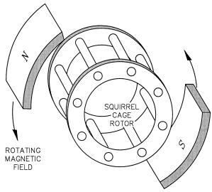
FIGURE 6-3
Squirrel cage rotor of the induction machine under rotating magnetic field.
the induction machine. The angular speed of the rotating magnetic field is called the synchronous speed. It is denoted by Ns and is given by the following:
NS |
= 60 |
f |
revolutions per minute (rpm) |
(6-1) |
|
||||
|
|
p |
|
|
where f = frequency of the stator excitation p = number of magnetic pole pairs.
The stator coils are embedded in slots of high-permeability magnetic core to produce the required magnetic field intensity with low exciting current.
The rotor, however, has a completely different structure. It is made of solid conducting bars embedded in the slots of a magnetic core. The bars are connected together at both ends by the conducting end rings (Figure 6-3). Because of its resemblance, the rotor is called the squirrel cage rotor, or the cage rotor in short.
6.2.2Working Principle
The stator magnetic field is rotating at the synchronous speed determined by Equation 6-1. This field is conceptually represented by the rotating magnets in Figure 6-3. The relative speed between the rotating field and the rotor induces the voltage in each rotor turn linking the stator flux φ. The magnitude
© 1999 by CRC Press LLC
of the induced voltage is given by Faraday’s law of electromagnetic induction, namely:
e = − |
dφ |
(6-2) |
|
dt |
|||
|
|
where φ = the magnetic flux linking the rotor turn.
This voltage in turn sets up the circulating current in the rotor. The electromagnetic interaction of the rotor current and the stator flux produces the
torque. The amplitude of this torque is given by the following: |
|
|
|
T = K Φ I2 cos φ2 |
(6-3) |
where K = constant of proportionality |
|
|
Φ = amplitude of the stator flux wave |
|
|
I2 |
= amplitude of induced current in the rotor bars |
|
φ2 |
= phase angle by which the rotor current lags the rotor voltage. |
|
The rotor will accelerate under this torque. If the rotor was on frictionless bearings with no mechanical load attached, it is completely free to rotate with zero resistance. Under this condition, the rotor will attain the same speed as the stator field, namely, the synchronous speed. At this speed, the current induced in the rotor speed is zero, no torque is produced and none is required. The rotor finds equilibrium at this speed and will continue to run at the synchronous speed.
If the rotor is now attached to a mechanical load such as a fan, it will slow down. The stator flux, which always rotates at the constant, synchronous speed, will have relative speed with respect to the rotor. As a result, the electromagnetically induced voltage, current, and torque are produced in the rotor. The torque produced must equal that needed to drive the load at that speed. The machine works as the motor in this condition.
If we attach the rotor to a wind turbine and drive it faster than the synchronous speed, the induced current and the torque in the rotor reverse the direction. The machine now works as the generator, converting the mechanical power of the turbine into electrical power delivered to the load connected to the stator terminals. If the machine was connected to a grid, it would feed power into the grid.
Thus, the induction machine can work as the electrical generator only at speeds higher than the synchronous speed. The generator operation, for that reason, is often called the super-synchronous speed operation of the induction machine.
As described above, the induction machine needs no electrical connection between the stator and the rotor. Its operation is entirely based on the electromagnetic induction, hence, the name. The absence of rubbing electrical contacts and simplicity of its construction make the induction generator very
© 1999 by CRC Press LLC
robust, reliable, and a low-cost machine. For this reason, it is widely used in numerous applications in the industry.
The working principle of the induction machine can be seen as the transformer. The high voltage coil on the stator is excited and the low voltage coil on the rotor is shorted on itself. The power from one to the other can flow in either direction. The theory of operation of the transformer, therefore, holds true when modified to account for the relative motion between the stator and the rotor. This motion is expressed in terms of the slip of the rotor relative to the synchronously rotating magnetic field.
6.2.3Rotor Speed and Slip
The slip of the rotor is defined as the ratio of the speed of the rotating magnetic field sweeping past the rotor and the synchronous speed of the stator magnetic field. That is,
s = |
Ns |
− Nr |
(6-4) |
|
|
Ns
where s = slip of the rotor
Ns = synchronous speed = 60·f/p Nr = rotor speed.
The slip is generally considered positive in the motoring operation. In the generator mode, the slip would therefore be negative. In both the motoring mode and the generating mode, higher rotor slips induce higher current in the rotor and higher electromechanical power conversion. In both modes, the value of the slip is generally a few to several percent. Higher slips result in greater electrical loss, which must be effectively dissipated from the rotor to keep the operating temperature below the allowable limit.
The heat is removed from the machine by the fan blades attached to one end-ring of the rotor. The fan is enclosed in a shroud at the end. The forced air travels axially along the machine exterior, which has fins to increase the dissipation area. Figure 6-4 is an exterior view of a 150 kW induction machine showing the end shroud and the cooling fins running axially. Figure 6-5 is a cutaway view of the machine interior of a 2 MW induction machine.
The induction generator feeding the 60 or 50 Hz grid must run at speed higher than 3,600 rpm in a two-pole design, 1,800 rpm in a four-pole design, and 1,200 rpm in a six-pole design. The wind turbine speed, on the other hand, varies from a few hundred rpm in the kW range machines to a few tens of rpm in the MW rage machines. The wind turbine therefore must interface the generator via a mechanical gear. Since this somewhat degrades the efficiency and reliability, many small stand-alone plants operate with custom designed generators operating at lower speed without the mechanical gear.
© 1999 by CRC Press LLC
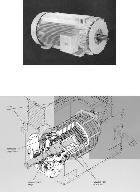
FIGURE 6-4
A 150 kW induction machine. (Source: General Electric Company, Fort Wayne, IN.)
FIGURE 6-5
Two MW induction machine. (Source: Teco Westinghouse Motor Company, Round Rock, Texas, With permission.)
© 1999 by CRC Press LLC