

FIGURE 6-10
Torque versus slip characteristic of induction generator under load.
of rotation of the magnetic flux wave with respect to the rotor. The torsional stress on the turbine blades and the hub, however, may limit the braking torque.
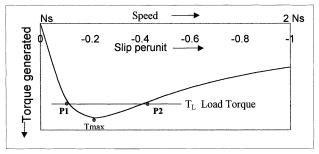
The torque-slip characteristic in the generating mode is separately shown in Figure 6-10. If the generator is loaded at constant load torque TL , it has two possible points of operation, P1 and P2. Only one of these two pints, P1, is stable. Any perturbation in speed around point P1 will produce stabilizing torque to bring it back to P1. The figure also shows the limit to which the generator can be loaded. The maximum torque it can support is called the breakdown torque, which is shown as Tmax . If the generator is loaded under a constant torque above Tmax , it will become unstable and stall, draw excessive current, and destroy itself thermally if not properly protected.
6.2.8Transients
The induction generator may experience the following three types of transient currents:
Starting Transient: In the grid-connected system, the induction generator is started as the motor in starting the turbine from rest to the super-synchro- nous speed. Then only it is switched to the generating mode, feeding power to the grid. If full voltage is applied during starting, the motor draws high starting current at zero speed when the slip is one and the rotor resistance is the least. The starting inrush current can be five to seven times the rated current, causing overheating problems, particularly in large machines. Moreover, as seen in Figure 6-11, the torque available to accelerate the rotor may be low, taking a long time to start. This also adds into the heating problem. For this reason, the large induction machine is often started with a soft-start circuit, such as the voltage reducing autotransformer or the star-delta starter. The modern method of starting is to apply reduced voltage of variable frequency maintaining a constant volts/hertz ratio. This method starts the machine with the least mechanical and thermal stresses.
© 1999 by CRC Press LLC

FIGURE 6-11
Induction machine starting and accelerating characteristic.
Reswitching Transient: A severe transient current can flow in the system if the induction generator operating in a steady state suddenly gets disconnected due to a system fault or any other reason, and then reconnected by an automatic reswitching. The magnitude of the current depends on the instant of the voltage wave when the generator gets reconnected to the grid. The physical appreciation of this transient comes from the constant flux linkage theorem. A coil having no resistance keeps its flux linkage constant. Since the winding resistance is small compared to the inductance in most electrical machines, the theorem of the constant flux linkage holds, at least in the beginning of the fault. If the reswitching was done when the stator and rotor voltages were in phase opposition, large transient currents are established to maintain the flux linkage, which then decays slowly to small values after tens of milliseconds. Meanwhile, the transient electromechanical torque may be large enough to give the machine and the tower a severe jolt. The actual amplitude and sign of the first peak of the transient torque are closely dependent on the rotor speed and duration of the interruption. In the worst case, the first peak may reach 15 times the rated full-load torque. Frequent faults of this nature can cause shaft breakage due to fatigue stresses, particularity at the coupling with the wind turbine.
Short Circuit: When a short circuit fault occurs at or near the generator terminals, the machine significantly contributes to the system fault current, particularly if it is running on light load. The short circuit current is always
© 1999 by CRC Press LLC