- •Preface
- •About the Author
- •About the Book
- •Acknowledgment
- •Contents
- •1.1 Industry Overview
- •1.2 Incentives for Renewables
- •1.3 Utility Perspective
- •1.3.1 Modularity
- •1.3.2 Emission-Free
- •References
- •2.1 Wind in the World
- •2.3 Europe
- •2.4 India
- •2.5 Mexico
- •2.6 Ongoing Research and Development
- •References
- •3.1 Present Status
- •3.2 Building Integrated pv Systems
- •3.3 pv Cell Technologies
- •3.3.2 Polycrystalline and Semicrystalline
- •3.3.3 Thin Films
- •3.3.4 Amorphous Silicon
- •3.3.5 Spheral
- •3.3.6 Concentrated Cells
- •3.4 pv Energy Maps
- •References
- •5.1 System Components
- •5.1.1 Tower
- •5.1.2 Turbine Blades
- •5.1.3 Yaw Control
- •5.1.4 Speed Control
- •5.2 Turbine Rating
- •5.3 Electrical Load Matching
- •5.5 System Design Features
- •5.5.1 Number of Blades
- •5.5.2 Rotor Upwind or Downwind
- •5.5.3 Horizontal Axis Versus Vertical Axis
- •5.5.4 Spacing of the Towers
- •5.6 Maximum Power Operation
- •5.6.2 Peak Power Tracking Scheme
- •5.7 System Control Requirements
- •5.7.1 Speed Control
- •5.7.2 Rate Control
- •5.8 Environmental Aspects
- •5.8.1 Audible Noise
- •5.8.2 Electromagnetic Interference (EMI)
- •References
- •6.1 Electromechanical Energy Conversion
- •6.1.1 DC Machine
- •6.1.2 Synchronous Machine
- •6.1.3 Induction Machine
- •6.2 Induction Generator
- •6.2.1 Construction
- •6.2.2 Working Principle
- •6.2.3 Rotor Speed and Slip
- •6.2.4 Equivalent Circuit for Performance Calculations
- •6.2.8 Transients
- •References
- •7.1 Speed Control Regions
- •7.2 Generator Drives
- •7.3 Drive Selection
- •References
- •8.1 The pv Cell
- •8.2 Module and Array
- •8.3 Equivalent Electrical Circuit
- •8.4 Open Circuit Voltage and Short Circuit Current
- •8.6 Array Design
- •8.6.1 Sun Intensity
- •8.6.2 Sun Angle
- •8.6.3 Shadow Effect
- •8.6.4 Temperature Effect
- •8.6.5 Effect of Climate
- •8.6.6 Electrical Load Matching
- •8.6.7 Sun Tracking
- •8.7 Peak Power Point Operation
- •8.8 pv System Components
- •References
- •9.1 Energy Collection
- •9.1.1 Parabolic Trough
- •9.1.2 Central Receiver
- •9.1.3 Parabolic Dish
- •9.2 Solar II Power Plant
- •9.3 Synchronous Generator
- •9.3.1 Equivalent Electrical Circuit
- •9.3.2 Excitation Methods
- •9.3.3 Electrical Power Output
- •9.3.4 Transient Stability Limit
- •9.4 Commercial Power Plants

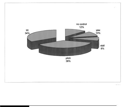
FIGURE 5-7
Speed control methods used in small to medium size turbines.
5.2Turbine Rating
The wind turbines are manufactured in sizes ranging from a few kW for stand-alone remote applications to a couple of MW each for utility scale power generation. The grid-connected turbine as large as 2 MW capacity was installed in 1979 on Howard Knob Mountain in the United States, and 3 MW capacity was installed in 1988 at Berger Hill in the United Kingdom.
The method of assessing the nominal rating of the wind turbine has no globally acceptable standard. The difficulty arises because the power output of the turbine depends on the square of the rotor diameter and the cube of the wind speed. The rotor of a given diameter will, therefore, generate different power at different wind speed. The turbine that can generate 300 kW at 7 m/s would produce 450 kW at 8 m/s wind. What rating should then be assigned to this turbine? Should we also specify the “rated speed”? Early wind turbine designers created a rating system that specified the power output at some arbitrary wind speed. This method did not work well as everyone could not agree on one speed to specify the power rating. The “rated” wind speeds varied from 10 to 15 m/s under this practice. Manufacturers are
© 1999 by CRC Press LLC
lax on providing the higher side of the wind speed, claiming greater output from the same design.
To avoid such rating confusion, some European manufacturers refer to only the rotor diameter. But the confusion continues as to the maximum power the machine can generate under the highest wind speed the turbine can continuously operate. Many manufacturers have, therefore, adopted the combined rating designations — the wind turbine diameter following the generator peak electrical rating. For example, the 300/30 wind system means 300 kW electrical generator and 30-meter diameter turbine.
The specific rated capacity (SRC) is often used as a comparative index of the wind turbine designs. It is defined as follows:
SRC = |
Generator electrical capacity |
(5-1) |
|
Rotor swept area |
|||
|
|
For the 300/30 wind turbine, the specific rated capacity is 300/π 152 = 0.42 kW/m2. The specific rated capacity increases with the diameter, giving a favorable economy of scale to large machine. It ranges from approximately 0.2 kW/m2 for 10-meter diameter rotor to 0.5 kW/m2 for 40-meter diameter rotor. Some aggressively rated turbines have SRC of 0.7 kW/m2, and some reaching as high as 1.0 kW/m2. The operating stresses in rotor blades of the high SRC are high, generally resulting in shorter fatigue life. All stress concentration regions are carefully identified and eliminated in high SCR designs. Modern design tools, such as the finite element stress analysis and the modal vibration analysis can be of great help in the rotor design.
The turbine rating is important as it indicates to the system designer how to size the induction generator, the plant’s transformer, connecting cables to the substation, and the transmission link interfacing the grid. The power system must be sized on the peak capacity of the generator, and the generator is rated in a different manner than the wind turbine. The turbine power depends on the cube of the wind speed. The system design engineer is, therefore, required to match the turbine and the generator performance characteristics. This means selecting the rated speed of the turbine to match with the generator. Since the gearbox and the generator are manufactured only in discrete sizes, selecting the turbine rated speed can be complex. The selection process goes through several iterations, trading the cost with benefit of the available speeds. Selecting a low rated speed would result in wasting much energy at high winds. On the other hand, if the rated speed is high, the rotor efficiency will suffer most of the times.
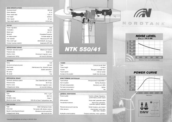
Figure 5-8 is an example of the summary data sheet of the 550/41 kW/m wind turbine manufactured by Nordtank Energy Group of Denmark. Such data is used in the preliminary design of the overall system. The specific rated capacity of this machine is 0.415. It has the cut-in wind speed of 5 m/s, the cutout speed of 25 m/s and it reaches the peak power at 15 m/s.
© 1999 by CRC Press LLC

LLC Press CRC by 1999 ©
FIGURE 5-8
Technical data sheet of a 550 kW/41-meter diameter wind turbine, with power level and noise level. (Source: Nordtank Energy Group, Denmark. With permission.)

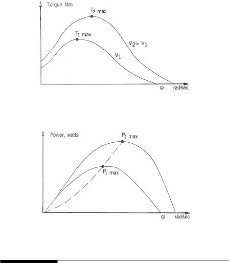
FIGURE 5-9
Wind turbine torque versus rotor speed characteristic at two wind speeds V1 and V2.
FIGURE 5-10
Wind turbine power versus rotor speed characteristic at two wind speeds V1 and V2.
5.3Electrical Load Matching
The typical turbine torque versus rotor speed is plotted in Figure 5-9. It shows a small torque at zero speed, rising to a maximum value before falling to nearly zero when the rotor just floats with the wind. Two such curves are plotted for different wind speeds V1 and V2, with V2 being higher than V1. The corresponding powers versus rotor speed at the two wind speeds are plotted in Figure 5-10. As the mechanical power converted into the electrical power is given by the product of the torque Τ and the angular speed ω, the power is zero at zero speed, and again at high speed with zero torque. The maximum power is generated at rotor speed somewhere in between, as
marked by P1max and P2max for speeds V1 and V2, respectively. The speed at the maximum power is not the same speed at which the torque is maximum.
© 1999 by CRC Press LLC

The operating strategy of a well-designed wind power system is to match the load on the electrical generator so that the rotor operates continuously at speeds as close as possible to the Pmax points. Since the Pmax point changes with the wind speed, the rotor speed must therefore be adjusted in accordance with the wind speed to make the rotor work continuously at Pmax.
5.4Variable-Speed Operation
At a given site, the wind speed can vary from zero to high gust. As discussed in Chapter 4, the Rayleigh statistical distribution is found to be the best approximation to represent the wind speed at most sites. It varies over a wide range. Earlier in Chapter 4, we defined the tip-speed ratio as follows:
TSR = |
Linear speed of the blade outer most tip |
= ω R |
(5-2) |
|
Free upstream wind velocity |
||||
|
V |
|
where R and ω are the rotor radius and the angular speed, respectively. For a given wind speed, the rotor efficiency Cp varies with TSR as shown
in Figure 5-11. The maximum value of Cp occurs approximately at the same wind speed that gives peak power in the power distribution curve of Figure 5-10. To capture the high power at high wind, the rotor must also turn at high speed, keeping the TSR constant at the optimum level.
Three system performance attributes are related to the TSR:
•The centrifugal mechanical stress in the blade material is proportional to the TSR. The machine working at a higher TSR is stressed more. Therefore, if designed for the same power in the same wind speed, the machine operating at a higher TSR would have slimmer rotor blades.
•The ability of a wind turbine to start under load is inversely proportional to the design TSR. As this ratio increases, the starting torque produced by the blade decreases.
•As seen above, the TSR is also related to the operating point for
extracting the maximum power. The maximum rotor efficiency Cp is achieved at a particular TSR, which is specific to the aerodynamic design of a given turbine. The TSR needed for the maximum power extraction ranges from nearly one for multiple-blade, slow-speed machines to nearly six for modern high-speed, two-blade machines.
The wind power system design must optimize the annual energy capture at a given site. The only operating mode for extracting the maximum energy is to vary the turbine speed with varying wind speed such that at all times the TSR is continuously equal to that required for the maximum power
© 1999 by CRC Press LLC
