

5
Wind Power System
The wind power system is fully covered in this and the following two chapters. This chapter covers the overall system level performance, design considerations and trades. The electrical generator is covered in the next chapter and the speed control in Chapter 7.
5.1System Components
The wind power system is comprised of one or more units, operating electrically in parallel, having the following components:
•the tower.
•the wind turbine with two or three blades.
•the yaw mechanism such as the tail vane.
•the mechanical gear.
•the electrical generator.
•the speed sensors and control.
The modern system often has the following additional components:
•the power electronics.
•the control electronics, usually incorporating a computer.
•the battery for improving the load availability in stand-alone mode.
•the transmission link connecting to the area grid.
Because of the large moment of inertia of the rotor, the design challenges include the starting, the speed control during the power producing operation, and stopping the turbine when required. The eddy current or other type of brake is used to halt the turbine when needed for emergency or for routine maintenance. In the multiple tower wind farm, each turbine must
© 1999 by CRC Press LLC
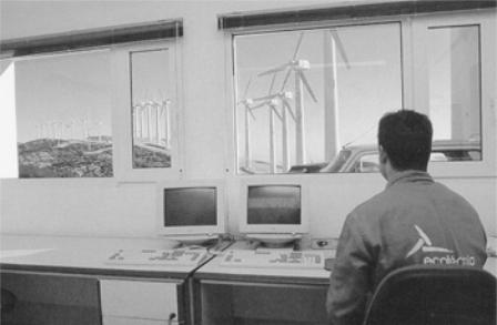
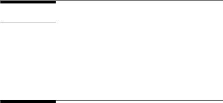
FIGURE 5-1
Control center at Baix Ebre wind farm in Catalonia, Spain. (Source: Institut Catalia d’Energia, Barcelona, Spain. With permission.)
have its own control system for operational and safety functions from a remote location (Figure 5-1).
5.1.1Tower
The wind tower supports the turbine and the nacelle containing the mechanical gear, the electrical generator, the yaw mechanism, and the stall control. The nacelle component details and the layout are shown in Figure 5-2. Figure 5-3 shows a large nacelle during installation. The height of tower in the past has been in the 20 to 50-meter range. For medium and large size turbines, the tower is slightly taller than the rotor diameter, as seen in the dimension drawing of a 600 kW wind turbine (Figure 5-4). Small turbines are generally mounted on the tower a few rotor diameters high. Otherwise, they would suffer due to the poor wind speed found near the ground surface (Figure 5-5).
Both steel and concrete towers are available and are being used. The construction can be tubular or lattice.
The main issue in the tower design is the structural dynamics. The tower vibration and the resulting fatigue cycles under wind speed fluctuation are avoided by design. This requires careful avoidance of all resonance frequencies of the tower, the rotor and the nacelle from the wind fluctuation frequencies.
© 1999 by CRC Press LLC
FIGURE 5-2
Nacelle details of a 150 kW/25 meter diameter turbine. (Source: Nordtank Energy Group/NEG Micon, Denmark. With permission.)
Sufficient margin must be maintained between the two sets of frequencies in all vibrating modes.
The resonance frequencies of the structure are determined by complete modal analyses, leading to the eigenvectors and eigenvalues of complex matrix equations representing the motion of the structural elements. The wind fluctuation frequencies that are found form the measurements at the site under consideration. Experience on a similar nearby site can bridge a gap on the required information.
Big cranes are generally required to install wind towers. Gradually increasing tower height, however, is bringing a new dimension in the installation (Figure 5-6). Large rotors add to the transportation problem as well. Tillable towers to nacelle and rotors moving upwards along with the tower are among some of the newer developments in the wind tower installation. The offshore installation comes with its own challenge that must be met.
5.1.2Turbine Blades
The turbine blades are made of high-density wood or glass fiber and epoxy composites. Modern wind turbines have two or three blades. The steady
© 1999 by CRC Press LLC
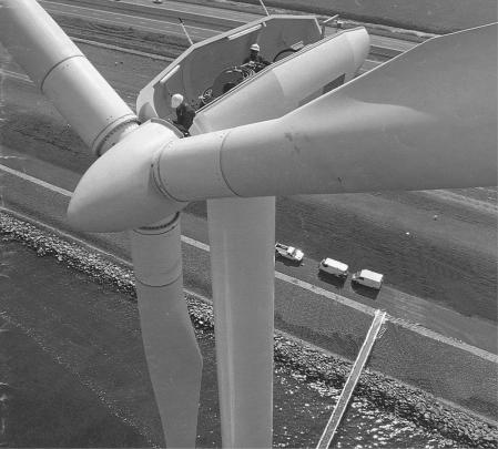
FIGURE 5-3
A large nacelle under installation. (Source: Nordtank Energy Group/NEG Micon, Denmark. With permission.)
mechanical stress due to centrifugal forces and fatigue under continuous vibrations make the blade design the weakest mechanical link in the system. Extensive design effort is needed to avoid premature fatigue failure of the blade.
The mechanical stress in the blade under gusty wind is kept under the allowable limit. This is achieved by controlling the rotor speed below the set limit. This not only protects the blades, but also protects the electrical generator from overloading and overheating. One method that has been used from the early designs and continues to be used today is the stall control. At stall, the wind flow ceases to be smooth around the blade contour, but separates before reaching the trailing edge. This always happens at high pitch angle. The blades experience high drag, thus lowering the rotor power output. The high pitch angle also produces high lift. The resulting load on the blade can cause a high level of vibration and fatigue, possibly leading to the mechanical failure. Regardless of the fixed or variable speed, the design engineer must deal with the stall forces. Researchers are moving from
© 1999 by CRC Press LLC
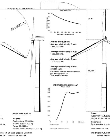
FIGURE 5-4
A 600 kW wind turbine and tower dimensions with specifications. (Source: Wind World Corporation, Denmark. With permission.)
the 2D to 3D stress analyses to better understand and design for such forces. As a result, the blade design is continually changing, particularly at the blade root where the loading is maximum due to the cantilever effect.
The aerodynamic design of the blade is important, as it determines the energy capture potential. The large and small machine blades have significantly different design philosophies. The small machine sitting on the tower
© 1999 by CRC Press LLC