

The maximum Cp region is the normal mode of operation, where the speed controller operates the system at the optimum constant Cp value stored in the system computer. Two alternative schemes of controlling the speed in this region were described in Section 5.6.
In the constant Cp region, the control system increases the rotor speed in response to the increasing wind speed only up to a certain limit (Figure 7-4). When this limit is reached, the control shifts into the speed-limiting region. The power coefficient Cp is no longer at the optimum value, and the rotor power efficiency suffers.
If the wind speed continues to rise, the systems will approach the power limitation of the electrical generator. When this occurs, the turbine speed is reduced, and the power coefficient Cp moves farther away from the optimum value. The generator output power remains constant at the design limit. When the speed limit and power limit cannot be maintained under extreme gust of wind, the machine is cut out of the power producing operation.
Two traditional methods of controlling the turbine speed and generator power output are as follows:
(1)The pitch control in which the turbine speed is controlled by controlling the blade pitch by mechanical and hydraulic means. The power fluctuates above and below the rated value as the blade pitch mechanism adjusts with changing wind speed. This takes some time because of the large inertia of the rotor. Figure 7-4 depicts variations in the wind speed, the pitch angle of the blades, the generator speed and the power output with respect to time in a fluctuating wind. The curves represent actual measurements on Vestas
1.65MW wind turbine with OptiSlip® (registered tradename of Vestas Wind Systems, Denmark). The generator power output is held constant even with 10 percent fluctuation in the generator speed, thus, minimizing the undesired fluctuations on grid. The elasticity of the system also reduces the stress on the turbine and the foundation.
(2)The stall control in which the turbine uses the aerodynamic stall to regulate speed in high winds. The power generation peaks somewhat higher than the rated limit, then declines until the cut-out wind speed is reached. Beyond that point, the turbine stalls and the power production drops to zero (Figure 7-5).
In both methods of speed regulation, the power output of most machines in practice is not as smooth. The theoretical considerations give only approximations of the power produced at any given instant. For example, the turbine can produce different power at the same speed depending on whether the speed is increasing or decreasing.
7.2Generator Drives
Selecting the operating speed of the generator and controlling it with changing wind speed must be determined early in the system design. This is
© 1999 by CRC Press LLC
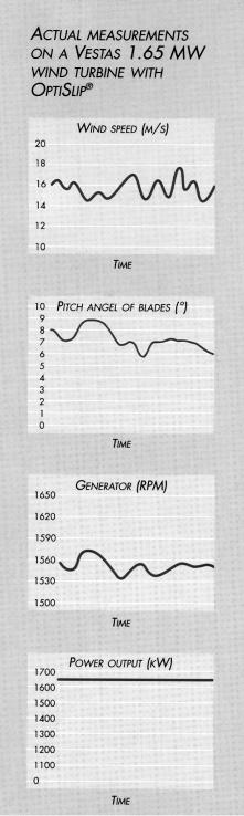
FIGURE 7-4
Wind speed, pitch angle, generator speed, and power output under fluctuating wind speed in 1650 kW turbine. (Source: Vestas Wind Systems, Denmark. With permission.)
© 1999 by CRC Press LLC
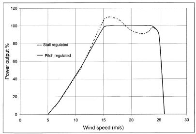
FIGURE 7-5
Generator output power variation with wind speed in the blade pitch-regulated and stallregulated turbines.
important, as it determines all major components and their ratings. The alternative strategies and the corresponding speed control methods fall in the following categories.
7.2.1One Fixed-Speed Drive
The fixed-speed operation of the generator naturally fits well with the induction generator, which is inherently a fixed-speed machine. However, the turbine speed is generally low, whereas the electrical generator works more efficiently at high speed. The speed match between the two is accomplished by the mechanical gear. The gearbox reduces the speed and increases the torque, thus improving the rotor power coefficient Cp. Under varying wind speed, the increase and decrease in electromagnetically converted torque and power are accompanied by the corresponding increase or decrease in the rotor slip with respect to the stator. The wind generator generally works at 1 to 2 percent slip. The higher value benefits the drive gear, but increases the electrical loss in the rotor, which leads to cooling difficulty.
The annual energy yield for a fixed-speed wind turbine must be analyzed with the given wind speed distribution at the site of interest. Since the speed is held constant, the turbine running above the rated speed is not a design concern. However, it is possible to generate electrical power above the rated capacity of the generator. When this happens, the generator is shut off by
© 1999 by CRC Press LLC
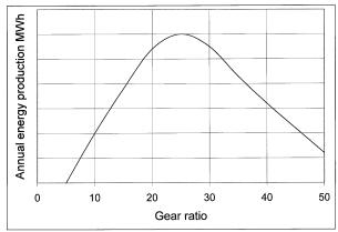
FIGURE 7-6
Annual energy production strongly varies with gear ratio for a given wind speed of 8 m/s.
opening the circuit breaker, thus shedding the load and dropping the system power generation to zero.
The major disadvantage of one fixed-speed operation is that it almost never captures the wind energy at the peak efficiency in terms of the rotor power coefficient Cp. The wind energy is wasted when the wind speed is higher or lower than the certain value selected as the optimum.
With the generator operating at constant speed, the annual energy production depends on the wind speed and the gear ratio. Figure 7-6 depicts the annual energy versus gear ratio relation typical of such systems. It is seen that the annual energy yield is highly dependent on the selected gear ratio. For the given wind-speed distribution in the figure, the energy production is maximum at the gear ratio of 20. When choosing the gear ratio, it is therefore important to consider the average wind speed at the specific site. The optimum gear ratio for the operation of the wind turbine varies from site to site.
Because of the low energy yield over the year, the fixed-speed drives are limited to small machines.
7.2.2Two Fixed-Speeds Drive
The two-speed machine increases the energy capture, reduces the electrical loss in the rotor and reduces the gear noise. The speed is changed by changing the gear ratio. The two operating speeds are selected to optimize the annual energy production with the wind speed distribution expected at the site. The annual power production varies with the gear ratio and the wind speed as seen in Figure 7-7. It is obvious from the figure that the peak power point wind speeds V1 and V2 with two-gear ratios must be on the opposite
© 1999 by CRC Press LLC
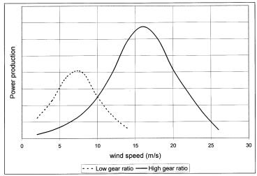
FIGURE 7-7
Power production probability distribution with wind speed with low and high gear ratios.
side of the expected annual average wind speed. For the specific example of Figure 7-7, the system is operated on the low-gear ratio for wind speed below 10 m/s, and on the high-gear ratio for wind speed above 10 m/s. The gear ratio is changed at 10 m/s in this example.
In some early American designs, two speeds were achieved by using two separate generators and switching between the generators by a belt drive.
An economic and efficient method is to design the induction generator to operate at two speeds. The cage motor with two separate stator windings of different pole numbers can run at two or more integrally related speeds. The pole-changing motor, on the other hand, has a single winding, the connection of which is changed to give different numbers of poles. Separate windings matching with the system requirement may be preferred where the speed change must be made without losing control of the machine. Separate windings are, however, difficult to accommodate.
In the pole-changing method with one winding, the stator is wound with coils that can be connected either in P or 2P number of poles. No changes are needed, nor possible, in the squirrel cage rotor. The stator connection which produces a higher pole number for low-speed operation is changed to one-half as many poles for high-speed operation. This maintains the tipspeed ratio near the optimum to produce high rotor power coefficient Cp. The machine, however, operates with only one-speed ratio of 2:1.
Figure 7-8 shows one phase of the pole changing stator winding. For the higher pole number, the coils are in series. For the lower number, they are in series-parallel. The resulting magnetic flux pattern corresponds to eight and four poles, respectively. It is common to use double layer winding, with 120° electrical span for the higher pole number. An important design
© 1999 by CRC Press LLC
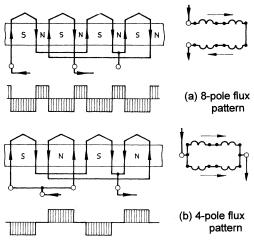
FIGURE 7-8
Pole-changing stator winding for speed ratio 2:1.
consideration in such windings is to limit the space harmonics, which may decrease the efficiency as the generator, and may also produce a tendency to crawl when using the machine as the motor during the start up operation.
The coil pitch of the stator winding is fixed once wound, but its electrical span depends on the number of poles. A coil pitch one-eighth of the circumference provides full-pitch coils for an eight-pole connection, two-thirds for a six-pole, and one-half for a four-pole connection. Too narrow a coil span must be avoided. For a 2:1 speed-ratio generator, a possible coil span is 1.33 pole-pitch for the larger and 0.67 for the smaller pole number. In each case, the coil span factor would be 0.87. Using the spans near 1 and 0.5, with the span factor of 1.0 and 0.71, one can avoid excessive leakage reactance in the lower-speed operation.
7.2.3Variable-Speed Using Gear Drive
The variable-speed operation using variable-gear ratio has been considered in the past, but have been found to add more problems than the benefits. Therefore, such drives are not generally used at present.
7.2.4Variable-Speed Using Power Electronics
The modern variable-speed drive uses power electronics to convert variable voltage, variable frequency output of the generator into the fixed voltage, fixed frequency output. The technology is similar to that used in the aircraft power system. The trend of using such a system is being propelled by the declining cost of the power semiconductors. Conventional silicon controlled rectifiers
© 1999 by CRC Press LLC
and inverters can be used, but the modern design in the wind industry appears to prefer pulse-width-modulated thyristors. The speed ratio is not limited in theory, but practical considerations limit the ratio to 3:1, which is wider than that obtainable using the pole-changing method described above and the Scherbius machine described later. The energy yield of the variable-speed system is higher. However, the added cost and the electrical loss in the power electronics partially offset the benefit. The cost and benefit trade is generally positive for large machines.
The power-electronics based variable-speed system introduces some system level issues not found in other systems. It produces high-frequency harmonics (electrical noise) in the network, which degrades the quality of power. Alternatively, for the same quality of power, it requires a higher degree of electrical filtering to meet the grid-quality requirement.
In addition to high annual energy production, the variable-speed power electronic system offers remotely adjustable and controllable quality of power. This has two major benefits not available in other systems:
•opportunity for remote control. This makes it attractive for offshore applications.
•fine-tuning for superior grid connection, making it better suited for meeting the demand of weak grids in developing countries like China and India.
7.2.5Scherbius Variable-Speed Drive
Compared to the variable-speed system using power electronics, the Scherbius machine offers lower cost and eliminates the power quality disadvantage. It has been used in hoist applications in factories and mines. Extending the analysis of the equivalent circuit described in Chapter 6, the speed of the induction machine can be changed by changing the rotor resistance or by injecting an external voltage of the frequency corresponding to the desired rotor slip. The squirrel cage construction does not allow such injection. Therefore, the wound rotor construction with slip rings is used (Figure 7-9). The rotor circuit is connected to an external variable frequency source via slip rings, and the stator is connected to the grid system. For this reason, the Scherbius machine is also called the doubly-fed induction machine. It is fed from both the stator and the rotor. The speed is controlled by adjusting the frequency of the external source of the rotor current. The range of variablespeed control using the Scherbius machines is generally limited to 2:1.
The concept was used in early turbines. The decreased reliability due to the rubbing electrical contacts at the slip rings had been a concern. However, some manufacturers appear to have resolved this concern, and are implementing the system in turbines with several hundred kW ratings. The need of the variable frequency source for the rotor adds into the cost and complexity. For large systems, however, the added cost may be less than the benefit of greater energy production of the variable-speed operation.
© 1999 by CRC Press LLC
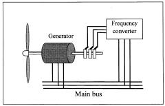
FIGURE 7-9
Scherbius adjustable-speed drive system injects variable frequency voltage in the wound rotor circuit.
7.2.6Variable-Speed Direct Drive
The generator that operates directly at the turbine speed is extremely attractive. This is possible particularity for small machines where the rotor speed is high. The direct drive eliminates the mechanical gear altogether, and needs no power electronics. This results in multiple benefits:
•lower nacelle weight.
•reduced noise and vibration.
•lower power loss by several percent.
•less frequent servicing requirement at the nacelle.
The last benefit is particularly attractive for offshore installation.
The low rotor-speed requirement for large rotors imposes a design limitation on the electrical machine. That is, the generator must have large numbers of poles. Such machines must have short pole-pitch, resulting in poor magnetic design. To circumvent such limitation, the permanent magnet and wound rotor synchronous machines are being considered for 1.5 MW direct drive generators. Another possible solution is the axial gap induction machine. It can be designed with a large number of poles with less difficulty compared to the conventional radial gap induction machine. The axial gap machine is being considered for direct drive marine propulsion, which is inherently a low-speed system. For small gearless wind drives, the axial-flux permanent magnet generator may find some interest for its simplicity. A 5 kW, 200 revolution-per-minute laboratory prototype of the axial-gap permanent magnet design has been recently tested,1 however, significant research and development effort is needed before the vari- able-speed direct drive systems can be commercially made available for large wind power systems.
© 1999 by CRC Press LLC