


Envisia HDL Modeling Reference
Verilog Modeling Styles
Modeling Combinational Logic
Verilog semantics require that all variables used on the left-hand side of a procedural assignment must be declared as reg (a storage data type as opposed to wire declaration which is a connection data type). However, not all variables declared as reg data type need to be implemented in hardware with a memory element (latch or flip-flop).
BuildGates synthesis software synthesizes combinational logic to implement a variable under any of the following conditions:
■The variable is unconditionally assigned a value before it is used and whenever any of the variables in the right-hand side expression change. For example, combinational logic is synthesized to implement variable z for the models below:
reg z;
always @ (a or b or c) begin
z = a + b + c;
end
a |
|
|
|
|
|
+ |
|
|
|
|
|
|
||
b |
|
|
z |
|
|
|
|||
c |
|
|
|
|
|
|
|
|
|
|
|
|
|
|
|
|
|
|
|
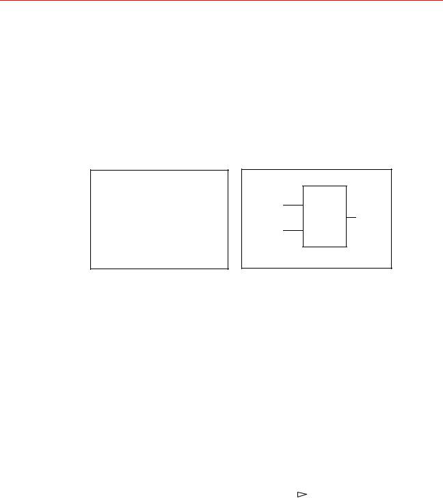
■The variable is conditionally assigned a value under all possible conditions whenever any of the variables in the right-hand side expression change. For example, combinational logic is synthesized to generate signal z for the models below:
reg z;
always @ (a or b or s)
begin
if (s)
z = a;
else
z = b;
end
s
a |
|
sel |
|
|
|
0 MUX |
|
z |
|
|
|
|||
b |
|
1 |
|
|
|
|
|
Register Inferencing
A register is a level sensitive (latch) or edge-triggered (flip-flop) memory element. Ambit
BuildGates synthesis infers registers from the syntax of the HDL and generates a sequential element table that reports the number and type of memory elements inferred for the model synthesized by the do_build_generic command.
September 2000 |
24 |
Product Version 4.0 |
Envisia HDL Modeling Reference
Verilog Modeling Styles
The following sections describe how registers are inferred:
■Latch Inference on page 25
■Flip-Flop Inference on page 25
Latch Inference
Ambit BuildGates synthesis infers a latch for a variable that is incompletely assigned, and that is updated whenever any of the variables that contribute to its value change (see example below).
reg dout;
always @ (din, en)
begin
if (en)
dout = din;
end
din D
Q dout
en EN
Signal dout is modified when en is high. The model does not specify what happens when en is low (or unknown). The default behavior implied by Verilog is that the signal dout retains its previous value. BuildGates synthesis software infers a latch to implement the variable dout.
Flip-Flop Inference
When an assignment is conditioned upon a rising or falling transition on a signal, an edgetriggered flip-flop is inferred to implement the variable on the left-hand side of the assignment. This is shown in the following example:
reg dout; |
|
|
|
|
|
|
|
always @ (posedge clk) |
|
|
|
|
|
|
|
|
din |
|
D |
Q |
|
dout |
|
begin |
|
|
|
||||
|
|
|
|||||
|
|
|
|
|
|
|
|
dout = din; |
|
|
|
|
|
|
|
end |
|
clk |
|
|
CLK |
|
|
|
|
|
|
|
|
||
|
|
|
|
|
|
|
|
|
|
|
|
|
|
|
|
September 2000 |
25 |
Product Version 4.0 |

Envisia HDL Modeling Reference
Verilog Modeling Styles
Synchronous set and reset on a Flip-Flop
A flip-flop with synchronous set and reset connections is synthesized when the model is written as follows:
reg dout;
always @ (posedge clk) if (set)
dout = 1’b1 ; else if (reset) dout = 1’b0 ;
else
dout = din;
The always block is triggered only on the rising edge of clk, but the assignment to dout is controlled by set and reset signals; dout is assigned the value of din only when set and reset are inactive.
Only single-bit controls are accepted for set and reset. See Synthesis Directives on page 31 for more information on controlling the set and reset connections for a flip-flop.
Asynchronous Operation On a Flip-Flop
A flip-flop with asynchronous operation is inferred when an assignment is conditioned upon multiple signal transitions. The asynchronous behavior is implemented in hardware through asynchronous set and reset pins on a flip-flop.
reg dout ;
always @(posedge clk or posedge set or posedge reset) if (set)
dout = 1’b1; else if (reset) dout = 1’b0;
else
dout = din;
The always block is triggered when a rising edge is detected on clk, set or reset. If set or reset is active low, then the event in the sensitivity list and the condition in the if statement should be negated.
always @(posedge clk or negedge set ...)
if (~set)
dout = 1’b1;
...
September 2000 |
26 |
Product Version 4.0 |