


Register and Three-State Inference
end rtl;
Register Name Type Width Bus MB AR AS SR SS ST
TEMP_reg |
Latch 1 |
- |
- N N - - - |
TEMP_reg
reset/set: none
Register Name Type Width Bus MB AR AS SR SS ST
Q_reg |
Latch 1 |
- - N N - - - |
Q_reg
reset/set: none
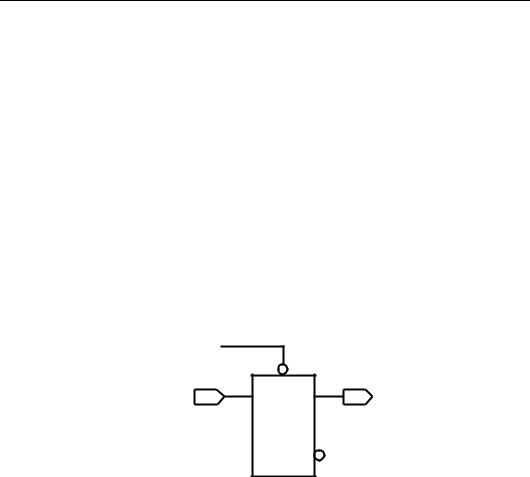
Figure 7-6 Two-Phase Clocks
Inferring Flip-Flops
Foundation Express can infer D flip-flops, JK flip-flops, and toggle flip-flops. The following sections provide details about each of these flip-flop types.
Many FPGA devices have a dedicated set/reset hardware resource that should be used. For this reason, you should infer asynchronous set/reset signals for all flip-flops in the design. Foundation Express will then use the global set/reset lines.
VHDL Reference Guide |
7-15 |

VHDL Reference Guide
Inferring D Flip-Flops
Foundation Express infers a D flip-flop whenever the condition of a wait or if statement uses an edge expression (a test for the rising or falling edge of a signal). Use the following syntax to describe a rising edge.
SIGNAL’event and SIGNAL = ’1’
Use the following syntax to describe a falling edge.
SIGNAL’event and SIGNAL = ’0’
If you are using the IEEE std_logic_1164 package, you can use the following syntax to describe a rising edge and a falling edge.
if (rising_edge (CLK)) then
if (falling_edge (CLK)) then
If you are using the IEEE std_logic_1164 package, you can use the following syntax for a bused clock. You can also use a member of a bus as a signal.
sig (3)’event and sig (3) = ’1’
rising_edge (sig(3))
A wait statement containing an edge expression causes Foundation Express to create flip-flops for all signals, and some variables are assigned values in the process. The following example shows the most common usage of the wait statement to infer a flip-flop.
process begin
wait until (edge);
...
end process;
An if statement implies flip-flops for signals and variables in the branches of the if statement. The following example shows the most common usages of the if statement to infer a flip-flop.
process (sensitivity_list) begin
if (edge)
...
end if; end process;
7-16 |
Xilinx Development System |

Register and Three-State Inference
process (sensitivity_list) begin
if (...) then
...
elsif (...)
...
elsif (edge) then
...
end if; end process;
You can sometimes use wait and if statements interchangeably. If possible, use the if statement, because it provides greater control over the inferred registers.
The following sections provide code examples, inference reports, and figures for these types of D flip-flops.
•Positive edge-triggered D flip-flop
•Positive edge-triggered D flip-flop using rising_edge
•Negative edge-triggered D flip-flop
•Negative edge-triggered D flip-flop using falling_edge
•D flip-flop with asynchronous set
•D flip-flop with asynchronous reset
•D flip-flop with asynchronous set and reset
•D flip-flop with synchronous set
•D flip-flop with synchronous reset
•D flip-flop with synchronous and asynchronous load
•Multiple flip-flops with asynchronous and synchronous controls
Positive Edge-Triggered D Flip-Flop When you infer a D flipflop, control the clock and data signals from the top-level design ports or through combinatorial logic. Clock and data signals that can be controlled ensure that simulation can initialize the design. If you cannot control the clock and data signals, infer a D flip-flop with asynchronous reset or set or with a synchronous reset or set.
The following example provides the VHDL template for a positive edge-triggered D flip-flop. Foundation Express generates the inference report shown following the example for a positive edge-trig-
VHDL Reference Guide |
7-17 |

VHDL Reference Guide
gered D flip-flop. The figure “Positive-Edge-Triggered D Flip-flop” shows the inferred flip-flop.
library IEEE ;
use IEEE.std_logic_1164.all;
entity dff_pos is
port (DATA, CLK : in std_logic; Q : out std_logic );
end dff_pos;
architecture rtl of dff_pos is begin
infer : process (CLK) begin
if (CLK’event and CLK = ’1’) then Q <= DATA;
end if;
end process infer;
end rtl;
The following example shows an inference report for a positive edgetriggered D flip-flop.
Register Name |
Type |
Width |
Bus |
MB |
AR |
AS |
SR |
SS |
ST |
|
|
|
|
|
|
|
|
|
|
Q_reg |
Flip-flop |
1 |
- |
- |
N |
N |
N |
N |
N |
|
|
|
|
|
|
|
|
|
|
Q_reg
set/reset/toggle: none
DATA |
Q |
CLK
X8595
Figure 7-7 Positive Edge-Triggered D Flip-Flop
Positive Edge-Triggered D Flip-Flop Using rising_edge The following example provides the VHDL template for a positive edge-
7-18 |
Xilinx Development System |

Register and Three-State Inference
triggered D flip-flop using the IEEE_std_logic_1164 package and rising_edge.
Foundation Express generates the inference report shown after the example. The figure following the inference report shows the inferred flip-flop.
library IEEE ;
use IEEE.std_logic_1164.all;
entity dff_pos is
port (DATA, CLK : in std_logic; Q : out std_logic );
end dff_pos;
architecture rtl of dff_pos is begin
infer : process (CLK) begin if (rising_edge (CLK)) then
Q <= DATA; end if;
end process infer; end rtl;
Register Name |
Type |
Width |
Bus |
MB |
AR |
AS |
SR |
SS |
ST |
|
|
|
|
|
|
|
|
|
|
Q_reg |
Flip-flop |
1 |
- |
- |
N |
N |
N |
N |
N |
|
|
|
|
|
|
|
|
|
|
Q_reg
set/reset/toggle: none
VHDL Reference Guide |
7-19 |

VHDL Reference Guide
DATA |
Q |
CLK 

X8595
Figure 7-8 Positive Edge-Triggered D Flip-Flop Using rising_edge
Negative Edge-Triggered D Flip-Flop The following example provides the VHDL template for a negative edge-triggered D flipflop. Foundation Express generates the inference report following the example for a negative edge-triggered D flip-flop. The figure “Negative Edge-Triggered D Flip-Flop” shows the inferred flip-flop.
library IEEE;
use IEEE.std_logic_1164.all;
entity dff_neg is
port (DATA, CLK : in std_logic; Q : out std_logic );
end dff_neg;
architecture rtl of dff_neg is begin
infer : process (CLK) begin
if (CLK’event and CLK = ’0’) then Q <= DATA;
end if;
end process infer; end rtl;
7-20 |
Xilinx Development System |
Register and Three-State Inference
The following example shows an inference report for a negative edge-triggered D flip-flop.
|
Register Name |
Type |
|
Width |
Bus |
MB |
AR |
|
AS |
SR |
SS |
ST |
||||
|
|
|
|
|
|
|
|
|
|
|
|
|
|
|
|
|
|
Q_reg |
Flip-flop |
1 |
- |
|
|
- |
|
N |
|
N |
N |
N |
N |
||
|
|
|
|
|
|
|
|
|
|
|
|
|
|
|
|
|
|
Q_reg |
|
|
|
|
|
|
|
|
|
|
|
|
|
|
|
|
set/reset/toggle: none |
|
|
|
|
|
|
|
|
|
|
|
||||
DATA |
|
|
|
|
|
|
|
|
|
Q |
|
|
|
|
||
|
|
|
|
|
|
|
|
|
|
|
|
|
||||
|
|
|
|
|
|
|
|
|
|
|
|
|
||||
CLK 
X8596
Figure 7-9 Negative Edge-Triggered D Flip-Flop
Negative Edge-Triggered D Flip-Flop Using falling_edge The following example provides the VHDL template for a negative edgetriggered D flip-flop using the IEEE_std_logic_1164 package and falling_edge.
Foundation Express generates the inference report shown after the following example. The figure following the inference report shows the inferred flip-flop.
library IEEE;
use IEEE.std_logic_1164.all;
entity dff_neg is
port (DATA, CLK : in std_logic; Q : out std_logic );
end dff_neg;
architecture rtl of dff_neg is begin
infer : process (CLK) begin if (falling_edge (CLK)) then
Q <= DATA;
VHDL Reference Guide |
7-21 |

VHDL Reference Guide
end if;
end process infer; end rtl;
Register Name |
Type |
Widt |
Bus |
MB |
AR |
AS |
SR |
SS |
ST |
|
|
h |
|
|
|
|
|
|
|
|
|
|
|
|
|
|
|
|
|
Q_reg |
Flip-flop |
1 |
- |
- |
N |
N |
N |
N |
N |
|
|
|
|
|
|
|
|
|
|
Q_reg
set/reset/toggle: none
DATA 
CLK 
X8596
Figure 7-10 Negative Edge-Triggered D Flip-Flop Using falling_edge
D Flip-Flop with Asynchronous Set The following example provides the VHDL template for a D flip-flop with an asynchronous set. Foundation Express generates the inference report shown following the example for a D flip-flop with asynchronous set. The figure “D Flip-Flop with Asynchronous Set” shows the inferred flipflop.
library IEEE;
use IEEE.std_logic_1164.all;
entity dff_async_set is
port (DATA, CLK, SET : in std_logic; Q : out std_logic );
end dff_async_set;
7-22 |
Xilinx Development System |
Register and Three-State Inference
architecture rtl of dff_async_set is begin
infer : process (CLK, SET) begin if (SET = ’0’) then
Q <= ’1’;
elsif (CLK’event and CLK = ’1’) then Q <= DATA;
end if;
end process infer; end rtl;
The following example shows an inference report for a D flip-flop with asynchronous set.
Register Name |
Type |
Width |
Bus |
MB |
AR |
AS |
SR |
SS |
ST |
|
|
|
|
|
|
|
|
|
|
Q_reg |
Flip-flop |
1 |
- |
- |
N |
Y |
N |
N |
N |
|
|
|
|
|
|
|
|
|
|
Q_reg
Async-set: SET’
SET 
DATA |
Q |
CLK 

X8597
Figure 7-11 D Flip-Flop with Asynchronous Set
D Flip-Flop with Asynchronous Reset The following example provides the VHDL template for a D flip-flop with an asynchronous reset. Foundation Express generates the inference report following the example for a D flip-flop with asynchronous reset. The figure “D Flip-Flop with Asynchronous Reset” shows the inferred flip-flop.
library IEEE;
use IEEE.std_logic_1164.all;
VHDL Reference Guide |
7-23 |

VHDL Reference Guide
entity dff_async_reset is
port (DATA, CLK, RESET : in std_logic; Q : out std_logic );
end dff_async_reset;
architecture rtl of dff_async_reset is begin
infer : process ( CLK, RESET) begin if (RESET = ’1’) then
Q <= ’0’;
elsif (CLK’event and CLK = ’1’) then Q <= DATA;
end if;
end process infer;
end rtl;
The following example shows an inference report for a D flip-flop with asynchronous reset.
Register Name |
Type |
Width |
Bus |
MB |
AR |
AS |
SR |
SS |
ST |
|||||
|
|
|
|
|
|
|
|
|
|
|
|
|
|
|
Q_reg |
Flip-flop |
1 |
|
- |
- |
Y |
N |
N |
N |
N |
||||
|
|
|
|
|
|
|
|
|
|
|
|
|
|
|
Q_reg |
|
|
|
|
|
|
|
|
|
|
|
|
|
|
Async-reset: RESET |
|
|
|
|
|
|
|
|
|
|||||
DATA |
|
|
|
|
|
|
|
|
|
Q |
||||
|
|
|
|
|
|
|
|
|
||||||
|
|
|
|
|
|
|
|
|
||||||
CLK |
|
|
|
|
|
|
|
|
|
|
|
|
|
|
|
|
|
|
|
|
|
|
|
|
|
|
|
|
|
RESET |
|
|
|
|
|
|
|
|
X8598 |
|||||
|
|
|
|
|
|
|
|
|||||||
|
|
|
|
|
|
|
|
|||||||
|
|
|
|
|
|
|
|
|
||||||
Figure 7-12 D Flip-Flop with Asynchronous Reset
D Flip-Flop with Asynchronous Set and Reset The following example provides the VHDL template for a D flip-flop with active high asynchronous set and reset pins. The template uses the one_hot
7-24 |
Xilinx Development System |

Register and Three-State Inference
attribute to prevent priority encoding of the set and reset signals. If you do not specify the one_hot attribute, the reset signal has priority, because it is used as the condition for the if clause. Foundation Express generates the inference report following the example for a D flip-flop with asynchronous set and reset. The figure “D Flip-Flop with Asynchronous Set and Reset” shows the inferred flip-flop.
Note: Most FPGA architectures do not have a register with an asynchronous set and asynchronous reset cell available. For this reason, avoid this construct.
library IEEE, synopsys;
use IEEE.std_logic_1164.all; use synopsys.attributes.all;
entity dff_async is
port (DATA, CLK, SET, RESET : in std_logic; Q : out std_logic );
attribute one_hot of SET, RESET : signal is ”true”; end dff_async;
architecture rtl of dff_async is begin
infer : process (CLK, SET, RESET) begin if (RESET = ’1’) then
Q <= ’0’;
elsif (SET = ’1’) then Q <= ’1’;
elsif (CLK’event and CLK = ’1’) then Q <= DATA;
end if;
end process infer;
end rtl;
The following example shows an inference report for a D flip-flop with asynchronous set and reset.
Register Name |
Type |
Width |
Bus |
MB |
AR |
AS |
SR |
SS |
ST |
|
|
|
|
|
|
|
|
|
|
Q_reg |
Flip-flop |
1 |
- |
- |
Y |
Y |
N |
N |
N |
|
|
|
|
|
|
|
|
|
|
Q_reg
Async-reset: RESET
Async-set: SET
Async-set and Async-reset ==> Q: X
VHDL Reference Guide |
7-25 |

VHDL Reference Guide
SET |
|
DATA |
Q |
CLK |
|
RESET 
X8599
Figure 7-13 D Flip-flop with Asynchronous Set and Reset
D Flip-Flop with Synchronous Set or Reset The previous examples illustrate how to infer a D flip-flop with asynchronous controls— one way to initialize or control the state of a sequential device. You can also synchronously reset or set the flip-flop (see the following two examples in the next section). The sync_set_reset attribute directs Foundation Express to the synchronous controls of the sequential device.
When the target technology library does not have a D flip-flop with synchronous reset, Foundation Express infers a D flip-flop with synchronous reset logic as the input to the D pin of the flip-flop. If the reset (or set) logic is not directly in front of the D pin of the flip-flop, initialization problems can occur during gate-level simulation of the design.
D Flip-Flop with Synchronous Set The following example provides the VHDL template for a D flip-flop with synchronous set. Foundation Express generates the inference report shown following the example for a D flip-flop with synchronous set. The figure “D Flip-Flop with Synchronous Set” shows the inferred flip-flop.
library IEEE, synopsys;
use IEEE.std_logic_1164.all; use synopsys.attributes.all; entity dff_sync_set is
port (DATA, CLK, SET : in std_logic;
7-26 |
Xilinx Development System |

Register and Three-State Inference
Q : out std_logic );
attribute sync_set_reset of SET : signal is ”true”; end dff_sync_set;
architecture rtl of dff_sync_set is begin
infer : process (CLK) begin
if (CLK’event and CLK = ’1’) then if (SET = ’1’) then
Q <= ’1’; else
Q <= DATA; end if;
end if;
end process infer;
end rtl;
The following example shows an inference report for a D flip-flop with synchronous set.
Register Name |
Type |
Width |
Bus |
MB |
AR |
AS |
SR |
SS |
ST |
|
|
|
|
|
|
|
|
|
|
Q_reg |
Flip-flop |
1 |
- |
- |
N |
N |
N |
Y |
N |
|
|
|
|
|
|
|
|
|
|
Q_reg
Sync-set: SET
SET
Q
DATA
CLK 
X8600
Figure 7-14 D Flip-Flop with Synchronous Set
D Flip-Flop with Synchronous Reset The following example provides the VHDL template for a D flip-flop with synchronous reset. Foundation Express generates the inference report shown following the example for a D flip-flop with synchronous reset. The figure “D Flip-Flop with Synchronous Reset” shows the inferred flip-flop.
VHDL Reference Guide |
7-27 |

VHDL Reference Guide
library IEEE, synopsys;
use IEEE.std_logic_1164.all; use synopsys.attributes.all;
entity dff_sync_reset is
port (DATA, CLK, RESET : in std_logic; Q : out std_logic );
attribute sync_set_reset of RESET : signal is ”true”;
end dff_sync_reset;
architecture rtl of dff_sync_reset is begin
infer : process (CLK) begin
if (CLK’event and CLK = ’1’) then if (RESET = ’0’) then
Q <= ’0’; else
Q <= DATA; end if;
end if;
end process infer;
end rtl;
The following example shows an inference report for a D flip-flop with synchronous reset.
Register Name |
Type |
Width |
Bus |
MB |
AR |
AS |
SR |
SS |
ST |
|
|
|
|
|
|
|
|
|
|
Q_reg |
Flip-flop |
1 |
- |
- |
N |
N |
Y |
N |
N |
|
|
|
|
|
|
|
|
|
|
Q_reg
Sync-reset: RESET’
RESET
Q
DATA
CLK 
X8601
Figure 7-15 D Flip-Flop with Synchronous Reset
7-28 |
Xilinx Development System |

Register and Three-State Inference
D Flip-Flop with Synchronous and Asynchronous Load D flipflops can have asynchronous or synchronous controls. You must check the asynchronous conditions before you check the synchronous conditions.
The following example provides the VHDL template for a D flip-flop with synchronous load (called SLOAD) and an asynchronous load (called ALOAD). Foundation Express generates the inference report shown following the example for a D flip-flop with synchronous and asynchronous load. The figure “D Flip-Flop with Synchronous and Asynchronous Load” shows the inferred flip-flop.
library IEEE;
use IEEE.std_logic_1164.all;
entity dff_a_s_load is
port(SLOAD, ALOAD, ADATA, SDATA, CLK : in std_logic;
Q : out std_logic ); end dff_a_s_load;
architecture rtl of dff_a_s_load is begin
infer: process (CLK, ALOAD) begin if (ALOAD = ’1’) then
Q <= ADATA;
elsif (CLK’event and CLK = ’1’) then if (SLOAD = ’1’) then
Q <= SDATA; end if;
end if;
end process infer;
end rtl;
The following example shows an inference report for a D flip-flop with synchronous and asynchronous load.
Register Name |
Type |
Widt |
Bus |
MB |
AR |
AS |
SR |
SS |
ST |
|
|
h |
|
|
|
|
|
|
|
|
|
|
|
|
|
|
|
|
|
Q_reg |
Flip-flop |
1 |
- |
- |
N |
N |
N |
N |
N |
|
|
|
|
|
|
|
|
|
|
Q_reg
set/reset/toggle: none
VHDL Reference Guide |
7-29 |

VHDL Reference Guide
ALOAD |
|
|
SLOAD |
Q |
|
SDATA |
||
|
||
CLK |
|
ADATA
X8602
Figure 7-16 D Flip-Flop with Synchronous and Asynchronous Load
Multiple Flip-Flops with Asynchronous and Synchronous Controls If a signal is synchronous in one process but asynchronous in another, use the sync_set_reset_local and async_set_reset_local attributes to direct Foundation Express to the correct implementation.
In the following example, block infer_sync uses the reset signal as a synchronous reset, and the process infer_async uses the reset signal as an asynchronous reset. Foundation Express generates the inference report shown following the example for multiple flip-flops with asynchronous and synchronous controls. The figure “Multiple Flipflops with Asynchronous and Synchronous Controls” shows the resulting design.
library IEEE, synopsys;
use IEEE.std_logic_1164.all; use synopsys.attributes.all;
entity multi_attr is
port (DATA1, DATA2, CLK, RESET, SLOAD : in std_logic;
Q1, Q2 : out std_logic ); end multi_attr;
architecture rtl of multi_attr is
attribute async_set_reset_local of infer_async :
7-30 |
Xilinx Development System |
Register and Three-State Inference
label is ”RESET”;
attribute sync_set_reset_local of infer_sync : label is ”RESET”;
begin
infer_sync: process (CLK) begin
if (CLK’event and CLK = ’1’) then if (RESET = ’0’) then
Q1 <= ’0’;
elsif (SLOAD = ’1’) then Q1 <= DATA1;
end if; end if;
end process infer_sync;
infer_async: process (CLK, RESET) begin if (RESET = ’0’) then
Q2 <= ’0’;
elsif (CLK’event and CLK = ’1’) then if (SLOAD = ’1’) then
Q2 <= DATA2; end if;
end if;
end process infer_async;
end rtl;
The following example shows inference reports for multiple flip-flops with asynchronous and synchronous controls.
Register Name |
Type |
Width |
Bus |
MB |
AR |
AS |
SR |
SS |
ST |
|
|
|
|
|
|
|
|
|
|
Q1_reg |
Flip-flop |
1 |
- |
- |
N |
N |
Y |
N |
N |
|
|
|
|
|
|
|
|
|
|
Q1_reg |
|
|
|
|
|
|
|
|
|
Sync-reset: RESET’ |
|
|
|
|
|
|
|
||
|
|
|
|
|
|
|
|
|
|
Register Name |
Type |
Width |
Bus |
MB |
AR |
AS |
SR |
SS |
ST |
|
|
|
|
|
|
|
|
|
|
Q2_reg |
Flip-flop |
1 |
- |
- |
Y |
N |
N |
N |
N |
|
|
|
|
|
|
|
|
|
|
Q2_reg
Async-reset: RESET’
VHDL Reference Guide |
7-31 |