
- •About This Manual
- •Additional Resources
- •Manual Contents
- •Conventions
- •Typographical
- •Online Document
- •Using Foundation Express with VHDL
- •Hardware Description Languages
- •Typical Uses for HDLs
- •Advantages of HDLs
- •About VHDL
- •Foundation Express Design Process
- •Using Foundation Express to Compile a VHDL Design
- •Design Methodology
- •Design Descriptions
- •Entities
- •Entity Generic Specifications
- •Entity Port Specifications
- •Architecture
- •Declarations
- •Components
- •Concurrent Statements
- •Constant Declarations
- •Processes
- •Signal Declarations
- •Subprograms
- •Type Declarations
- •Examples of Architectures for NAND2 Entity
- •Configurations
- •Packages
- •Using a Package
- •Package Structure
- •Package Declarations
- •Package Body
- •Resolution Functions
- •Data Types
- •Type Overview
- •Enumeration Types
- •Enumeration Overloading
- •Enumeration Encoding
- •Enumeration Encoding Values
- •Integer Types
- •Array Types
- •Constrained Array
- •Unconstrained Array
- •Array Attributes
- •Record Types
- •Record Aggregates
- •Predefined VHDL Data Types
- •Data Type BOOLEAN
- •Data Type BIT
- •Data Type CHARACTER
- •Data Type INTEGER
- •Data Type NATURAL
- •Data Type POSITIVE
- •Data Type STRING
- •Data Type BIT_VECTOR
- •Unsupported Data Types
- •Physical Types
- •Floating-Point Types
- •Access Types
- •File Types
- •Express Data Types
- •Subtypes
- •Expressions
- •Overview
- •Operators
- •Logical Operators
- •Relational Operators
- •Adding Operators
- •Unary (Signed) Operators
- •Multiplying Operators
- •Miscellaneous Arithmetic Operators
- •Operands
- •Operand Bit-Width
- •Computable Operands
- •Aggregates
- •Attributes
- •Expressions
- •Function Calls
- •Identifiers
- •Indexed Names
- •Literals
- •Numeric Literals
- •Character Literals
- •Enumeration Literals
- •String Literals
- •Qualified Expressions
- •Records and Fields
- •Slice Names
- •Limitations on Null Slices
- •Limitations on Noncomputable Slices
- •Type Conversions
- •Sequential Statements
- •Assignment Statements and Targets
- •Simple Name Targets
- •Indexed Name Targets
- •Slice Targets
- •Field Targets
- •Aggregate Targets
- •Variable Assignment Statements
- •Signal Assignment Statements
- •Variable Assignment
- •Signal Assignment
- •if Statements
- •Evaluating Conditions
- •Using the if Statement to Infer Registers and Latches
- •case Statements
- •Using Different Expression Types
- •Invalid case Statements
- •loop Statements
- •Basic loop Statement
- •while...loop Statements
- •for...loop Statements
- •Steps in the Execution of a for...loop Statement
- •for...loop Statements and Arrays
- •next Statements
- •exit Statements
- •Subprograms
- •Subprogram Always a Combinatorial Circuit
- •Subprogram Declaration and Body
- •Subprogram Calls
- •Procedure Calls
- •Function Calls
- •return Statements
- •Procedures and Functions as Design Components
- •Example with Component Implication Directives
- •Example without Component Implication Directives
- •wait Statements
- •Inferring Synchronous Logic
- •Combinatorial Versus Sequential Processes
- •null Statements
- •Concurrent Statements
- •Overview
- •process Statements
- •Combinatorial Process Example
- •Sequential Process Example
- •Driving Signals
- •block Statements
- •Nested Blocks
- •Guarded Blocks
- •Concurrent Versions of Sequential Statements
- •Concurrent Procedure Calls
- •Concurrent Signal Assignments
- •Simple Concurrent Signal Assignments
- •Conditional Signal Assignments
- •Selected Signal Assignments
- •Component Instantiation Statements
- •Direct Instantiation
- •generate Statements
- •for...generate Statements
- •Steps in the Execution of a for...generate Statement
- •Common Usage of a for...generate Statement
- •if...generate Statements
- •Register and Three-State Inference
- •Register Inference
- •The Inference Report
- •Latch Inference Warnings
- •Controlling Register Inference
- •Inferring Latches
- •Inferring Set/Reset (SR) Latches
- •Inferring D Latches
- •Inferring Master-Slave Latches
- •Inferring Flip-Flops
- •Inferring D Flip-Flops
- •Inferring JK Flip-Flops
- •Inferring Toggle Flip-Flops
- •Getting the Best Results
- •Understanding Limitations of Register Inference
- •Three-State Inference
- •Reporting Three-State Inference
- •Controlling Three-State Inference
- •Inferring Three-State Drivers
- •Inferring a Simple Three-State Driver
- •Three-State Driver with Registered Enable
- •Three-State Driver Without Registered Enable
- •Writing Circuit Descriptions
- •How Statements Are Mapped to Logic
- •Design Structure
- •Adding Structure
- •Using Variables and Signals
- •Using Parentheses
- •Using Design Knowledge
- •Optimizing Arithmetic Expressions
- •Arranging Expression Trees for Minimum Delay
- •Sharing Common Subexpressions
- •Changing an Operator Bit-Width
- •Using State Information
- •Propagating Constants
- •Sharing Complex Operators
- •Asynchronous Designs
- •Don’t Care Inference
- •Using Don’t Care Default Values
- •Differences Between Simulation and Synthesis
- •Synthesis Issues
- •Feedback Paths and Latches
- •Fully Specified Variables
- •Asynchronous Behavior
- •Understanding Superset Issues and Error Checking
- •Foundation Express Directives
- •Notation for Foundation Express Directives
- •Foundation Express Directives
- •Translation Stop and Start Pragma Directives
- •synthesis_off and synthesis_on Directives
- •Resolution Function Directives
- •Component Implication Directives
- •Foundation Express Packages
- •std_logic_1164 Package
- •std_logic_arith Package
- •Using the Package
- •Modifying the Package
- •Data Types
- •UNSIGNED
- •SIGNED
- •Conversion Functions
- •Arithmetic Functions
- •Example 10-1: Binary Arithmetic Functions
- •Example 10-2: Unary Arithmetic Functions
- •Comparison Functions
- •Example 10-3: Ordering Functions
- •Example 10-4: Equality Functions
- •Shift Functions
- •ENUM_ENCODING Attribute
- •pragma built_in
- •Type Conversion
- •numeric_std Package
- •Understanding the Limitations of numeric_std package
- •Using the Package
- •Data Types
- •Conversion Functions
- •Resize Function
- •Arithmetic Functions
- •Comparison Functions
- •Defining Logical Operators Functions
- •Shift Functions
- •Rotate Functions
- •Shift and Rotate Operators
- •std_logic_misc Package
- •ATTRIBUTES Package
- •VHDL Constructs
- •VHDL Construct Support
- •Design Units
- •Data Types
- •Declarations
- •Specifications
- •Names
- •Identifiers and Extended Identifiers
- •Specifics of Identifiers
- •Specifics of Extended Identifiers
- •Operators
- •Shift and Rotate Operators
- •xnor Operator
- •Operands and Expressions
- •Sequential Statements
- •Concurrent Statements
- •Predefined Language Environment
- •VHDL Reserved Words
- •Examples
- •Moore Machine
- •Mealy Machine
- •Read-Only Memory
- •Waveform Generator
- •Smart Waveform Generator
- •Definable-Width Adder-Subtracter
- •Count Zeros—Combinatorial Version
- •Count Zeros—Sequential Version
- •Soft Drink Machine—State Machine Version
- •Soft Drink Machine—Count Nickels Version
- •Carry-Lookahead Adder
- •Carry Value Computations
- •Implementation
- •Serial-to-Parallel Converter—Counting Bits
- •Input Format
- •Implementation Details
- •Serial-to-Parallel Converter—Shifting Bits
- •Programmable Logic Arrays

Concurrent Statements
For more information about arrays, see “Array Types” section of the “Data Types” chapter.
if...generate Statements
The syntax follows.
label: if expression generate { concurrent_statement }
end generate [ label ] ;
•label identifies (names) this statement.
•expression is any expression that evaluates to a Boolean value.
•concurrent_statement is any of the statements described in this chapter, including other generate statements.
Note: Unlike the if statement described in the “if Statements” section of the “Sequential Statements” chapter, the if...generate statement has no else or elsif branches.
You can use the if...generate statement to generate a regular structure that has different circuitry at its ends. Use a for...generate statement to iterate over the desired width of a design and use a set of if...generate statements to define the beginning, middle, and ending sets of connections.
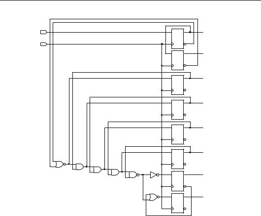
The following example shows a technology-independent description of an N-bit serial-to-parallel converter. Data is clocked into an N-bit buffer from right to left. On each clock cycle, each bit in an N-bit buffer is shifted up 1 bit, and the incoming DATA bit is moved into the low-order bit. The resulting design follows the example.
entity CONVERTER is generic(N: INTEGER := 8);
port(CLK, DATA: in BIT;
CONVERT: buffer BIT_VECTOR(N-1 downto 0)); end CONVERTER;
architecture BEHAVIOR of CONVERTER is signal S : BIT_VECTOR(CONVERT’range);
begin
G: for I in CONVERT’range generate
G1: -- Shift (N-1) data bit into high-order bit if (I = CONVERT’left) generate
VHDL Reference Guide |
6-23 |

VHDL Reference Guide
process begin
wait until (CLK’event and CLK = ‘1’); CONVERT(I) <= S(I-1);
end process; end generate G1;
G2: -- Shift middle bits up if (I > CONVERT’right and
I < CONVERT’left) generate
S(I) <= S(I-1) and CONVERT(I);
process begin
wait until (CLK’event and CLK =’1’); CONVERT(I) <= S(I-1);
end process; end generate G2;
G3: -- Move DATA into low-order bit if (I = CONVERT’right) generate
process begin
wait until (CLK’event and CLK = ‘1’); CONVERT(I) <= DATA;
end process;
S(I) <= CONVERT(I); end generate G3;
end generate G; end BEHAVIOR;
6-24 |
Xilinx Development System |

Concurrent Statements
DATA |
|
CLK |
FD1 |
|
|
|
FD1 |
|
FD1 |
|
FD1 |
|
FD1 |
NR2 |
FD1 |
|
|
AN2 |
|
AN2 |
|
AN2 |
IV |
|
ND2 |
|
FD1 |
|
NR2 |
|
FD1 |
X8619 |
|
CONVERT [0]
CONVERT [1]
CONVERT [2]
CONVERT [3]
CONVERT [4]
CONVERT [5]
CONVERT [6]
CONVERT [7]
Figure 6-11 Design of N-Bit Serial-to-Parallel Converter
VHDL Reference Guide |
6-25 |

VHDL Reference Guide
6-26 |
Xilinx Development System |