

Photochemistry_of_Organic
.pdfLight Sources, Filters and Detectors |
75 |
Figure 3.3 Relative spectral energy distribution of a 125 W medium-pressure Helios Italquartz Hg lamp and transmission curves of glass cut-off filters: quartz (—), Vycor (- - -), Pyrex ( ) and a band-pass filter [a solution of Cr(SO4)2 12H2O (15% w/v) in 0.5 M H2SO4 (– –). Adapted from Ace Glass Inc. Catalogue and ref. 157
The working temperature of tungsten-filament incandescent lamps lies between 2200 and 3000 K. Therefore, they emit light mostly in the visible and infrared parts of the spectrum. Such a source of radiation may be useful in photoreactions of coloured chromophores, for example in the photodissociation of bromine or chlorine molecules to initiate photohalogenation reactions (Section 6.6.1).
Figure 3.4 Typical spectral irradiance of 200 W Hg(Xe) (—) and 150 W Xe (- - -) lamps. Adapted by permission from Newport Corp. Oriel product line
76 |
Techniques and Methods |
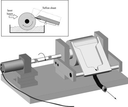
Lasers (see Special Topic 3.1) are mostly used in photochemistry for time-resolved measurements (Sections 3.5 and 3.7), but can be highly useful for preparative experiments or for the irradiation of samples in remote places such as NMR or EPR cavities, because they produce highly intense, strictly monochromatic and parallel beams. Pulsed lasers can give rise to absorption of two or more photons by a single molecule or to re-excitation of short-lived intermediates, thereby forming products that are different from those obtained by continuous irradiation. Pulsed lasers may also be advantageous when the photoproduct is also sensitive to irradiation and secondary photolysis of the product cannot be avoided by choosing an appropriate wavelength. If the photoproduct is not formed within the duration of the laser pulse, a condition often met when the reaction proceeds through reactive intermediates or a triplet state, secondary photolysis can be completely avoided by irradiating each sample with only a single laser pulse. This is easily realized on a preparative scale with the aid of the simple device shown in Figure 3.5: the cylinder dips into a solution containing the substrate and, when rotated, picks up a film of the solution. The speed of rotation is adjusted to the repetition frequency of the laser. A collector arm skims off the film with a thin Teflon sheet before the cylinder surface dips back into the bath. The whole device may be kept under a Plexiglas box equipped with a quartz window for irradiation under an inert gas atmosphere. A DC motor, such as available in toy model building shops, drives the cylinder and allows for simple adjustment of the rotating speed by changing the applied voltage.
Figure 3.5 Apparatus for preparative photolysis with pulsed lasers

Light Sources, Filters and Detectors |
77 |
Special Topic 3.1: Lasers
Lasers emit coherent electromagnetic radiation in a monochromatic beam of low divergence. Theodore Maiman built the first working laser in 1960.160 Currently, the most widespread use of lasers is in optical storage devices such as CD and DVD players, bar code readers, laser pointers and laser printers. Lasers are used for cutting and carving, for target identification and weapons delivery, for surgery and cosmetic applications and, of course, in photochemistry. They have become the foremost tool in photophysical and spectroscopic work, because of their well-defined wavelength and short pulse durations.
Lasers consist of a gain medium surrounded by a resonant optical cavity. The medium is pumped by an external energy source, usually by light from a flash lamp or from another laser or by an electric discharge. Laser emission occurs only when the number of particles in an excited state exceeds that in some lower energy state (population inversion, Figure 2.4) so that light amplification takes place in the cavity.
In the continuous wave (CW) mode of operation, the population inversion is maintained by a steady pump source and the laser output is essentially constant in time. In the pulsed mode, the output consists of short pulses; the length of the cavity defines the time elapsing between sequential pulses. In many applications, very short laser pulses are required. In a Q-switched laser, the population inversion is allowed to build up by keeping the cavity output mirrors reflective. Once the pump energy stored in the cavity is at the desired level, the reflectance of the exit is adjusted by an electroor acousto-optical Q-switch to release the light until the population inversion is depleted. Pulse lengths achieved in this way are on the order of 3–20 ns. Mode-locked lasers emit pulses of about 30 ps duration, which, using various tricks of the art, can be shortened to a few femtoseconds. Due to the energy–time uncertainty principle (Equation 2.1), a pulse of such short duration must contain a broad spectrum of wavelengths and the laser medium must have a broad gain profile to amplify them all. A suitable material is titanium-doped, artificially grown sapphire (Ti:sapphire).
Population inversion cannot be achieved in a two-level system, a material with two electronic states. At best, a nearly equal population of the two states is reached, resulting in optical transparency, when absorption by the ground state is balanced by stimulated emission from the excited state. An indirect method of populating the emitting excited state must be used. In a three-level laser (Figure 3.6, left), irradiation of the laser medium pumps an upper level 2, which is rapidly depleted by a nonradiative
2 |
2 |
fast |
fast |
3 |
3 |
h pump –h stimulated |
h pump –h stimulated |
|
4 |
|
fast |
1 |
1 |
Figure 3.6 Three-level (left) and four-level (right) laser systems

78 |
Techniques and Methods |
process populating a long-lived level 3. Thus stimulated emission induced by further pumping is avoided and the population of level 3 will eventually exceed that of the ground state. Benzophenone, for example, would fulfil these requirements, but its radiative rate constant of phosphorescence is very low. The chromium(III) ions in the ruby laser introduced by Maiman do the job. More efficient lasers can be built based on four-level systems. Here, the stimulated emission from level 3 reaches a low-lying level 4 that is rapidly depopulated to the ground level 1 by a second nonradiative process. Because only few atoms need be excited into the upper laser level to form a population inversion between levels 3 and 4, a four-level laser is much more efficient than a threelevel laser and most practical lasers are of this type.
Classical optics, so-called linear optics, assumes a linear response of transparent matter to electromagnetic radiation, as expressed in the refractive index. This description of the interaction light and matter retains only the first (linear) term of a Taylor expansion. Linear laws describing physical responses hold only up to a point; a well-known example is Hooke s law, describing the elasticity of a spring. The power of a single 1 mJ pulse released within a picosecond is 1 GW, equal to that of a modern nuclear power plant. With the high radiative powers of lasers, nonlinear responses necessitate the inclusion of higher (quadratic, cubic, etc.) terms. Nonlinear optics161 can produce unusual, but very useful, phenomena such as the frequency doubling (secondharmonic generation) in a BBO crystal, parametric down-conversion, optical parametric oscillators and the like, but also unwanted phenomena such as dielectric breakdown. Current activity to achieve light amplification in quantum dots holds promise for exciting new technical developments.162,163
As a consequence of Heisenberg s uncertainty principle, (Equation 2.1), ultrashort laser pulses are no longer highly monochromatic. Ti:sapphire femtosecond lasers can produce an octave-spanning spectrum directly from the oscillator and have led to the development of optical frequency combs.164 A mode-locked femtosecond laser maintains a short pulse circulating inside the optical cavity. With each round trip, an attenuated copy of the light pulse escapes so that the laser emits a regular train of ultrashort pulses. To measure the unknown frequency of a laser wave, the beam and the pulse train are superimposed with a beam splitter and a detector registers an interference signal. Optical frequency combs from mode-locked femtosecond lasers extend the limits of time and frequency metrology. Precise comparisons of optical resonance frequencies of atomic hydrogen and other atoms with the microwave frequency of a caesium atomic clock are establishing sensitive limits for conceivable slow variations of fundamental constants. Optical high harmonic generation is extending frequency comb techniques into the extreme ultraviolet region. Frequency comb techniques are also providing a key to attosecond science.
Some lasers that are frequently used in the photochemical laboratory and their properties are listed in Table 8.4.
Optical filters can modify the spectral output from spectrally broad light sources and essentially monochromatic light can be obtained from light sources with several sharp but widely separated emission lines, such as the low-pressure mercury arcs. Commercially available glass filters and readily prepared filter solutions are inexpensive alternatives to

Light Sources, Filters and Detectors |
79 |
monochromators. The most common cut-off (long-wavelength pass) filters are the glass of which the photochemical apparatus (Section 3.2) consists, such as lamp envelopes, immersion wells, test-tubes, and so on. An additional glass filter can be introduced between the source of the radiation and the sample. Fused quartz and fused silica have a very high UV transmission; they cut off below 180 nm and, depending on thickness and quality, also partly below 250 nm, while they are almost fully transparent above 250 nm (Figure 3.3). Vycor, a glass with good temperature and thermal shock resistance, can also be used for irradiation near and above 250 nm, while Pyrex is commonly utilized when wavelengths >290 nm are required. Many different shortor long-wavelength pass and bandpass filters are available commercially and their optical parameters can be found in the manufacturers catalogues. Dichroic filters are thin-film dielectric mirrors, which selectively allow light of a narrow range of wavelengths to pass. Because unwanted wavelengths are reflected rather than absorbed, dichroic filters do not absorb much energy and consequently do not heat up or age much during prolonged operation.
Solution filters are readily prepared in any photochemical laboratory. Their compositions and optical properties are available throughout the literature.137,157,158 Figure 3.3
shows, for example, the transmission curve of a band-pass solution filter made of Cr(SO4)2 dissolved in dilute aqueous H2SO4, which transmits radiation at 325 20 nm. As a result, the 313.9 nm band, available in the emission spectrum of medium-pressure mercury lamps, can be isolated. However, some of the reported solutions have limited photochemical stability and should be regularly checked for transmittance.
Pure solvents may also act as optical filters; for example, methanol and benzene cut off most of the radiation below 205 and 280 nm, respectively (Table 3.1). Their (internal) filter effect must be considered in planning photochemical experiments with solutions, because it may lower the reaction efficiencies.
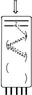
Photomultipliers are sensitive to light in the ultraviolet, visible and near-infrared regions, allowing for the detection of single photons. They consist of a glass or quartz vacuum tube housing a photocathode, a sequence of electrodes called dynodes and an anode (Figure 3.7). When an incident photon of sufficient energy, Ep hnth (photoelectric effect; see Figure 1.5), strikes the photocathode material, an electron is ejected and directed towards the electron multiplier, which consists of about eight dynodes, each of which is held at a more positive voltage than the previous one. The electron is accelerated
Table 3.1 Cut-off wavelengths of common solventsa
Solvent |
Cut-off wavelength/nm |
|
|
Water |
185 |
Acetonitrile |
190 |
n-Hexane |
195 |
Methanol |
205 |
Diethyl ether |
215 |
Ethyl acetate |
255 |
Carbon tetrachloride |
265 |
Benzene |
280 |
Pyridine |
305 |
Acetone |
330 |
aAdapted from ref. 1.
80 |
Techniques and Methods |
light
photocathode
focusing electrode 1st dynode
2nd dynode
3rd dynode
etc
anode
Figure 3.7 Schematic diagram of a head-on photomultiplier tube
by an electric field. On striking the first dynode, more electrons are emitted and these in turn are accelerated towards the second dynode. The dynode chain produces an increasing number of electrons at each stage. Finally, the anode is reached, where the accumulation of charge results in a sharp current pulse indicating the arrival of a photon at the photocathode. Photomultipliers produce up to about 108 electrons per incident photon. The temporal half-width of a single pulse of electrons reaching the anode is on the order of 1 ns, which limits the time resolution of photomultipliers.
In photodiodes, light absorption promotes an electron from the valence band to the conduction band of a semiconductor, thereby creating a mobile electron and a positively charged site, an electron hole . When a voltage is applied (reverse bias, photoconductive mode), this will give rise to a photocurrent through the diode. A diode array consists of thousands of photosensitive diodes in a oneor two-dimensional matrix. Each diode may span only 100 mm2. The readout to store a digitized image can be done by measuring the charge required to reload a capacitor behind each irradiated diode [charge coupled device (CCD)] and is usually clocked to 30 Hz. Diode arrays have largely replaced light-sensitive films in photographic devices.
Image intensifiers, also called microchannel plate (MCP) detectors, are a twodimensional array of tubes (e.g. 1000 1000 on a chip of 2 2 cm) that also operate by the photoelectric effect. An image is projected on to the MCP. As a photon hits a photocathode on the detector plate, the metal ejects an electron that is accelerated in an electric field and amplified. The anode is a phosphorescent screen that emits up to 104 photons upon impact of the fast electrons generated from a single photoelectron. A green phosphor is generally used because the human eye is most sensitive to that colour. An amplified, but monochromatic, image is thereby recreated on the phosphor screen. MCPs are used in night vision devices and are sensitive up to the near-infrared region. The phosphor is often combined with a CCD camera to record the image. For time-resolved applications, MCPs can be gated with rise-times of about 1 ns by applying a counter voltage near the photocathode so that photoelectrons do not reach the accelerating field and the device remains opaque as long as the counter voltage is applied. This can be used to capture objects moving at high speed or for spectrographic flash photolysis. In

Light Sources, Filters and Detectors |
81 |
spectrographic applications, the output of a polychromator (essentially a monochromator with a wide exit hole instead of the slit selecting a single colour) is focused on to the MCP. The spectrum is separated in one dimension, so that the green phosphor shows red light on one side and blue light on the other. Images so obtained can be read by a CCD camera. The time resolution is limited by the gating of the MCP, not the slow read-out process of the CCD camera. Microchannel plate photomultipliers can achieve response times of 30 ps.
A streak camera transforms the temporal profile of a light pulse into a spatial profile on the detector. For example, a spectrally resolved light pulse from a fluorescent sample that is excited by a short pulse of light hits a one-dimensional photocathode array through a narrow slit along one direction. The photoelectrons are accelerated in a cathode ray tube and pass through a pair of plates that produce a rapidly rising electric field that deflects the electrons orthogonally to the slit. The phosphor screen at the end of the tube then shows the spectral distribution of the light pulse in one direction and the time-varying deflection of the electrons in the other. A CCD array is used to record the streak pattern on the screen, displaying both the temporal and the spectral profile of the light pulse. In order to record periodic phenomena, the streak camera needs to be triggered, like an oscilloscope. The time resolution of the fastest optoelectronic streak cameras is about 0.2 ps in single-pulse mode. Jitter of the source trigger and of the instrument response will, however, limit the time resolution of accumulated periodic signals to 10 ps or more.
Special Topic 3.2: Organic Light-Emitting Diodes (OLEDs)
Recommended textbook.165
Light-emitting diodes (LEDs) accompany our daily lives. They are often used as small indicator lights on electronic devices and increasingly in higher power applications such as flashlights and area lighting. The colour of the emitted light depends on the composition of the semiconducting material used and can range from the IR to the nearUV. Red LEDs became commercially available in the late 1960s and were commonly used in seven-segment displays. Later, other colours became widely available and appeared in many appliances. As the LED materials technology became more advanced, the light output was increased and LEDs became bright enough to be used for illumination. Low-cost efficient blue LEDs did not emerge until the early 1990s, completing the desired RGB colour triad (Section 1.3). High-brightness colours gradually emerged in the 1990s, permitting new designs for outdoor signage and huge video displays for billboards and stadiums.
In recent years, organic light-emitting diodes (OLEDs) have started to be commercially applied in bright displays and the future holds tremendous opportunity for their low cost and high performance. They may eventually replace the liquid crystal displays (LCDs) that require backlight, which are used in mobile devices such as cellular phones and laptop computers, and perhaps even the fluorescent and incandescent light sources used for illumination. LEDs and OLEDs emitting in the near-UV region have been developed and they are increasingly employed as light sources in photochemical equipment for preparative irradiation and for quantitative work such as quantum yield measurements.

82 |
Techniques and Methods |
|
|
|
|
R |
|
|
|
N |
N |
N |
O |
O |
|
||||
|
Ir+ |
Eu |
|
|
|
N |
N |
O |
O |
|
|
|||
|
N |
|
|
3 |
|
R |
|
|
|
Figure 3.8 Organic transition metal complex dopants used in OLEDs
The basic mechanism of electroluminescence involves charge carrier recombination in semiconductor materials forming an electron–hole pair (exciton; see Special Topic 6.29). Due to spin statistics (Section 2.2.1), the recombination of charge carriers in semiconductor materials leads to the formation of 25% singlet and 75% triplet excitons. The triplet excitons in LEDs are generally wasted as heat. In OLEDs, the energy is transferred to organic transition metal complex (Section 6.4.4) dopants containing heavy atoms that exhibit strong spin–orbit coupling (SOC) (Section 4.8). This opens a radiative path for T1 ! S0 emission. SOC also enhances S1 ! T1 ISC. Thus, all excitons can be converted to triplet states of transition metal complexes (triplet harvesting) with high quantum yields and submicrosecond lifetimes of emission (Figure 3.8). As a result, OLEDs can reach a four times greater efficiency than LEDs or OLEDs built with purely organic fluorescent emitters.
3.2 Preparative Irradiation
Whereas elaborate equipment and tools are needed to study the mechanisms of photochemical reactions, techniques to achieve preparative irradiations are relatively simple and cheap. Nevertheless, when photochemical transformations in solution are used for organic synthesis, several specific requirements have to be fulfilled. High chemical yields and reduction of side-product formation can be achieved, but photochemists have to be careful in choosing proper irradiation wavelengths and reactant concentrations, to
consider internal filter effects and whether oxygen needs to be removed during irradiation.156,158 The chemical reagent (initiator) is light; therefore, the reaction vessel
and any optical components (lenses) should be transparent to the wavelength range of interest. The products or intermediates formed in the course of the reaction may absorb at the wavelengths of irradiation. When their concentrations increase during the conversion, reaction efficiency may decrease and eventually stop. Side-reactions may be eliminated in some cases as shown in Figure 3.5 or by decreasing the reactant concentration, which also improves light penetration within the sample, but as a result larger volumes of the reaction mixture will be necessary. Since dioxygen is an efficient triplet quencher (Sections 2.2.5 and 6.7.1), it should usually be removed from the solution prior to irradiation. The most
Preparative Irradiation |
83 |
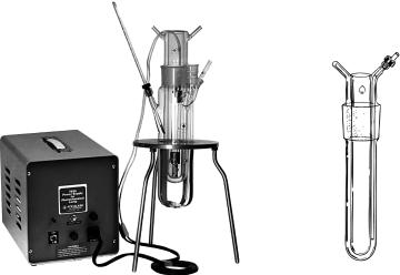
Figure 3.9 Left: a photochemical reactor with immersed configuration with the lamp and a power source. Right: detail of the immersion well. Reproduced by permission of Ace Glass Inc
common procedures are purging the solution with argon or nitrogen for several minutes before or during irradiation (which, at the same time, serves to mix the solution constantly) or the more rigorous but demanding freeze–pump–thaw method. The latter process requires several cycles of freezing the solution in liquid nitrogen, evacuation using a highvacuum pump and subsequent thawing when the vacuum inlet is closed, in order to remove completely all dissolved gases. The glass vessel with the frozen solution can then be torch sealed or closed with a good PTFE stopcock.
Photochemical reactors with immersed configuration (Figure 3.9) are the most common photochemical equipments in preparative irradiation.158 They usually consist of doublewalled immersion wells that provide water cooling of the lamp and filtering of the incident IR radiation. The sample solution, stirred by a magnetic bar typically under an argon atmosphere, is placed outside the lamp finger. The reactors are not ideal for photolysis experiments, in which a narrow excitation band is required. The construction material (Pyrex, quartz, etc.; Section 3.1) limits the wavelength range of irradiation, but a sleeve made of a filtering glass can be inserted between the lamp and the well wall. Furthermore, despite vigorous stirring, polymeric products may precipitate on to the reactor walls and absorb some of the light. This can be avoided by using falling-film or microstructured photochemical reactors,166 in which the reactant solution falls down along the irradiation well as a liquid film. The photolysed solution is continuously removed via an opening in the bottom of the reactor. Another advantage of falling-film reactors in photochemical reactions is that the thin layers allow extensive penetration and thus a more efficient use of light.
Photochemistry can also be carried out in a photoreactor of external configuration.158 This arrangement is very simple; the solution is held outside the source of irradiation. One option is to use an immersion well as shown in Figure 3.9, but the sample is placed in a separate vessel nearby. The whole setup can be immersed in a thermostated water or methanol bath to control the temperature of the reaction mixture. An external
84 |
Techniques and Methods |
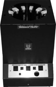
Figure 3.10 Rayonet photochemical reactor (external configuration). Reproduced by permission of Southern New England Ultra Violet Company
configuration reactor consisting of the reaction sample placed in the middle of an array of UV lamps is also commercially available (Figure 3.10).
A special photochemical reactor, utilizing electrodeless discharge lamps (EDLs), has been designed that generates UV radiation when placed in a microwave (MW) field.167–169
The EDL consists of a glass tube ( envelope ) filled with an inert gas and an excitable substance and sealed under a lower pressure of a noble gas. A low-frequency electromagnetic field (300–3000 MHz) triggers gas discharge, causing emission of UV–VIS radiation. An arrangement in which an EDL is placed inside the reaction solution has several advantages, such as simultaneous UV and MW irradiation of the sample, and is therefore capable of performing photochemistry at high temperatures and low cost.
Heterogeneous transition metal photocatalysis170 (Section 6.8.1) involves insoluble semiconductor metal oxides or sulfides which, upon irradiation, undergo interfacial electron transfer between the excited semiconductor surface and the reactants. The photolysis reactor usually consists of a thermostated transparent vessel containing a reaction mixture (e.g. TiO2 suspended in an aqueous solution of the reactant) under constant vigorous stirring. The source of visible or UV light is placed above or next to the reactor, like the photoreactor with an external configuration arrangement described above. Such devices are used for large-scale waste-water cleaning.
Organized and constrained media may provide cavities and surfaces, sometimes called
microreactors or nanoreactors,171 that can control the selectivity of photochemical reactions of reactants.172,173 There are many types of microreactors, for example,
molecular aggregates of micelles or monolayers, macrocyclic host cavities of crown ethers or cyclodextrins and microporous solid cavities and/or surfaces of zeolites, silica or