

MPLS Applications 17
If a labeled packet of 29 arrives on P1, it will be sent out Serial 0/1 as an unlabeled IP packet, as you can see in the following output:
P1#show mpls forwarding-table |
|
|
|
||
Local |
Outgoing |
Prefix |
Bytes tag |
Outgoing |
Next Hop |
tag |
tag or VC |
or Tunnel Id |
switched |
interface |
|
27 |
Pop tag |
192.168.1.16/30 |
0 |
Se0/1 |
point2point |
28 |
27 |
192.168.1.4/32 |
0 |
Se0/1 |
point2point |
29 |
Pop tag |
192.168.1.3/32 |
0 |
Se0/1 |
point2point |
31 |
Pop tag |
192.168.1.1/32 |
0 |
Se0/0 |
point2point |
What about a ping to the Serial 0/0 interface of P2 (192.168.1.13)? By looking at the labels of PE1, you can see that the packet will be sent out Serial 0/0 as an unlabeled IP packet, as you can see in the following output:
PE1#show mpls forwarding-table |
|
|
|
||
Local |
Outgoing |
Prefix |
Bytes tag |
Outgoing |
Next Hop |
tag |
tag or VC |
or Tunnel Id |
switched |
interface |
|
27 |
27 |
192.168.1.16/30 |
0 |
Se0/0 |
point2point |
28 |
28 |
192.168.1.4/32 |
0 |
Se0/0 |
point2point |
29 |
Pop tag |
192.168.1.2/32 |
0 |
Se0/0 |
point2point |
30 |
29 |
192.168.1.3/32 |
0 |
Se0/0 |
point2point |
32 |
Pop tag |
192.168.1.12/30 |
0 |
Se0/0 |
point2point |
Notice that the network in question is 192.168.1.12. Router P1 has a directly connected interface into this network and therefore does not need a labeled packet. Remember that penultimate hop popping is a time-saving mechanism.
MPLS Applications
One of the basic principles of MPLS is that packets are switched instead of routed. When a packet enters the service provider network from a customer, it is unlabeled IP. The router at the edge of the service provider network accepts the incoming unlabeled packet and applies a label.
The newly labeled packet follows an LSP through the service provider network and is label-switched, not forwarded. When the packet leaves the MPLS-enabled service provider network, the label is removed and it again becomes an unlabeled IP packet. This process is illustrated in Figure 1.10.
Copyright ©2002 SYBEX, Inc., Alameda, CA |
www.sybex.com |
18 Chapter 1 An Introduction to MPLS
You can see that the label is attached to the packet by the PE1 router as it enters the service provider network and is removed by the PE2 router as it is routed to the customer network.
F I G U R E 1 . 1 0 The MPLS process
|
|
|
IP |
|
L |
|
|
IP |
|
L |
|
|
IP |
|
L |
|
|
|
|
|
|
|
|
Serial |
0/0 |
0/0 |
Serial |
0/1 |
0/0 |
Serial |
0/1 |
|
0/0 |
|
|
|
|||||
|
Serial 0/1 |
|
Serial |
|
|
Serial |
|
|
|
Serial |
|
|
|
Serial 0/1 |
||||||
|
|
|
|
|
|
|
|
|
|
|
|
|
|
|
|
|
|
|||
IP |
PE1 |
|
|
|
P1 |
|
|
|
|
P2 |
|
|
|
PE2 |
|
IP |
||||
|
|
|
|
|
|
|
|
|
|
|
|
|
|
|
|
|
|
|
||
|
Serial 0 |
|
|
|
|
|
|
|
|
|
|
|
|
|
|
|
Serial 0 |
|||
CE1 |
|
|
|
|
|
|
|
|
|
|
|
|
|
|
|
|
|
|
|
CE2 |
Figure 1.10 is a logical, and not exact, representation of what happens to an IP packet as it moves through an MPLS-enabled service provider network.
Since packets receive labels at the edge of the network by the edge-LSR, and those labels are used by every LSR in the service provider network to switch traffic, many applications exist for MPLS, such as MPLS virtual private networks (VPNs), traffic engineering, and QoS.
MPLS and ATM
By turning a standard ATM Forum ATM switch into an ATM label switch router (ATM-LSR), it is possible to merge the ATM and IP worlds to provide end-to-end solutions. An ATM-LSR is an ATM switch that is capable of forwarding packets based on labels.
Chapter 3 provides more detail about implementing MPLS in an ATM network.
Overlay
When an ATM switch is enabled as an ATM-LSR, an overlay between service provider edge devices is no longer necessary. In Figure 1.8, all of the POP routers are edge-LSRs, and all the ATM switches are ATM-LSRs. Since
Copyright ©2002 SYBEX, Inc., Alameda, CA |
www.sybex.com |
MPLS Applications 19
every router in the network is running an Interior Gateway Protocol (IGP) such as Open Shortest Path First (OSPF) or Intermediate System-Intermediate System (IS-IS), POP routers now peer with ATM-LSRs directly instead of with each other in a full mesh.
As packets enter the network as unlabeled IP, the edge-LSR labels the packet and forwards it along the LSP. Figure 1.10 shows the labeled packet as it traverses the service provider network. The actual process is a little more complex than this example illustrates, but I want you to notice two very important areas in Figure 1.10:
Instead of an overlay, routers are directly connected to ATM-LSRs. Scalability is achieved by eliminating the need for a full mesh of VCs and reducing the numbers of neighbors that must be maintained by a routing protocol.
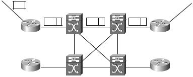
In Figure 1.11, packets enter the network as unlabeled IP. In this figure, the edge-LSR is in Raleigh, and it accepts the unlabeled IP packet and applies a label. Each ATM-LSR in the LSP uses the label to move packets.
F I G U R E 1 . 1 1 MPLS-enabled service provider network
IP |
Raleigh ATM |
|
Atlanta ATM |
|
|
||
|
IP L |
IP L |
IP L |
|
Raleigh |
|
Atlanta |
|
Miami |
|
Orlando |
|
Miami ATM |
|
Orlando ATM |
Quality of Service
MPLS addresses QoS by allowing packets to be classified at the network edge. Standard IP packets enter the network at an edge-LSR. The Experimental (EXP) field of the MPLS label stack is used to hold QoS information for use by MPLS-enabled devices along the LSP.
Copyright ©2002 SYBEX, Inc., Alameda, CA |
www.sybex.com |

20 Chapter 1 An Introduction to MPLS
The Experimental field is three bits in size. With three bits, a total of eight values are possible, but only six values are available for QoS. (The remaining two values are reserved for internal network use only.) The default operation is for the IP precedence value to be copied into the EXP field of the MPLS label stack. Table 1.2 shows the mappings of IP precedence to MPLS EXP.
T A B L E 1 . 2 Experimental-to-IP Precedence Mappings
Experimental |
IP Precedence |
Class |
|
|
|
7 |
7 |
Reserved |
6 |
6 |
Reserved |
5 |
5 |
Real-time |
4 |
4 |
|
3 |
3 |
|
2 |
2 |
|
1 |
1 |
Best effort |
|
|
|
With packets being classified at the network edge, it’s easier to provide for enforceable service-level agreements (SLAs). Queuing methods such as WRED and WFQ can be configured to operate using the EXP value in the MPLS label stack. With MPLS, every device in the network can enforce a consistent QoS policy regardless of whether they are routers or ATM switches.
Traffic Engineering
Routing protocols, by their use of metrics, attempt to determine the best (fastest) path for traffic to travel. For example, Figure 1.12 illustrates a simple routed network with various link speeds. In this figure, the objects R1 through R8 represent routers in the network, and the connections OC3 and OC12 represent the speed of the links between them.
Copyright ©2002 SYBEX, Inc., Alameda, CA |
www.sybex.com |

MPLS Applications 21
F I G U R E 1 . 1 2 A simple traffic-engineering network
|
OC3 |
OC3 |
OC3 |
|
|
|
|
R2 |
R3 |
|
|
OC3 |
R7 |
R1 |
OC12 |
|
OC12 |
R6 |
OC3 |
|
|
|
|
|
|||
|
|
OC12 |
|
|
|
|
|
R4 |
R5 |
|
|
|
R8 |
What is the best path for traffic to flow from R1 to R7? If the routing protocol is using bandwidth as a metric, then traffic will follow the path of
R1 to R4 to R5 to R6 to R7, as shown in Figure 1.13.
F I G U R E 1 . 1 3 Traffic flow from R1 to R7
|
OC3 |
OC3 |
OC3 |
|
|
|
|
R2 |
R3 |
|
|
OC3 |
R7 |
R1 |
OC12 |
|
OC12 |
R6 |
OC3 |
|
|
|
|
|
|||
|
R4 |
OC12 |
|
|
|
R8 |
|
R5 |
|
|
|
What if traffic is coming from R8 to R1? The best path from the perspective of a routing protocol is from R8 to R6 to R5 to R4 to R1, as shown in Figure 1.14.
F I G U R E 1 . 1 4 Traffic flow from R8 to R1
R2 |
R3 |
R7 |
R1 |
|
R6 |
R4 |
R5 |
R8 |
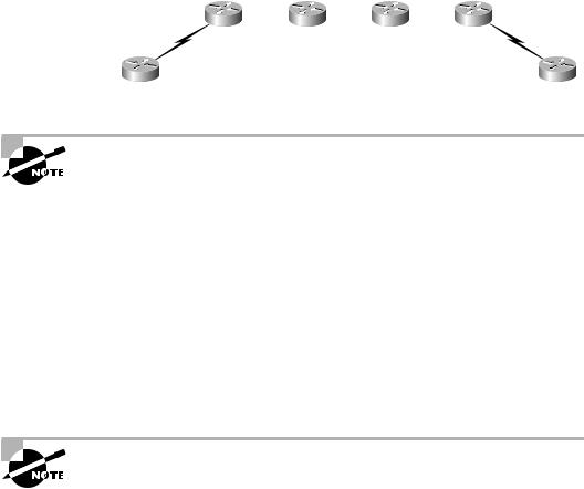
What about traffic coming from R7 destined for R1? Well, when the packet arrives at R6, it is sent along the same path as traffic from R8 to R1. From the routing protocol’s perspective, the best path is from R7 to R6 to R5 to R4 to R1, as shown in Figure 1.15.
Copyright ©2002 SYBEX, Inc., Alameda, CA |
www.sybex.com |

22 Chapter 1 An Introduction to MPLS
F I G U R E 1 . 1 5 Traffic flow from R7 to R1
R2 |
R3 |
R7 |
R1 |
|
R6 |
R4 |
R5 |
R8 |
Take a moment and look back at Figures 1.13, 1.14, and 1.15. Which routers are continually traversed regardless of source, destination, or direction? You should notice that R1, R4, R5, and R6 are continually used to move traffic across the network.
Traffic Engineering and Routing Protocols
If you are not a lord-high super-guru of routing, then there are a few issues that you should be aware of. First of all, with all the traffic being sent along the same path, it is possible for those links to become saturated. When a link becomes saturated, packets will be dropped. The alternate path (R1 to R2 to R3 to R4) will not be used.
Routing protocols find the best path to move the packet across the network. Routing protocols such as OSPF and IS-IS, which are used in the core of service provider networks, do not support unequal cost load balancing. In other words, even though there are two possible paths to get across the network, the routing protocol will only use one of them based on the metrics in use.
There is a little magic that you can do with routing protocols to try to make two unequal paths look equal. If the routing protocol has two equal routes across a network, it will load-balance. Be forewarned though: If you dabble in the black art of routing protocol manipulation and try to do this in a large network, it will become too much to manage.
Additionally, you could try to do some special policy-based routing. If you do this on your core routers, it will slow them down. You also might not want the job of managing such a solution.
Copyright ©2002 SYBEX, Inc., Alameda, CA |
www.sybex.com |
MPLS Applications 23
Which routers are never used to move user traffic across the network? You should notice in Figures 1.13, 1.14, and 1.15 that routers R2 and R3 are simply not used. To illustrate this, Table 1.3 describes the utilization of each of the links in this network.
T A B L E 1 . 3 Link Utilization
Link |
Usage |
|
|
R1 to R4 |
Utilized |
R4 to R5 |
Utilized |
R5 to R6 |
Utilized |
R1 to R2 |
Not Utilized |
R2 to R3 |
Not Utilized |
R3 to R4 |
Not Utilized |
|
|
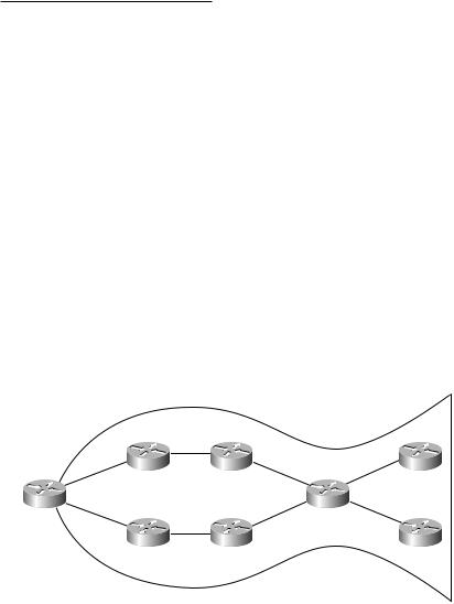
You can see that half of the links that are being paid for are used and half of the links that are being paid for are not being used. This problem is referred to as the fish. If you look at Figure 1.16, you can see why it is called the fish.
F I G U R E 1 . 1 6 The fish
R2 |
R3 |
R7 |
R1 |
|
R6 |
R4 |
R5 |
R8 |
Copyright ©2002 SYBEX, Inc., Alameda, CA |
www.sybex.com |