

- •Acknowledgments
- •Introduction
- •Assessment Test
- •Answers to Assessment Test
- •Service Provider Networks
- •Scalability
- •Traffic Engineering
- •Quality of Service
- •MPLS Label Stack
- •Shim Header
- •MPLS Architecture
- •Control
- •Forwarding
- •MPLS Label Switching
- •MPLS Network Components
- •Device Output
- •Label-Switched Paths
- •MPLS Applications
- •MPLS and ATM
- •Overlay
- •Quality of Service
- •Traffic Engineering
- •Summary
- •Exam Essentials
- •Key Terms
- •Review Questions
- •Answers to Review Questions
- •Routing Review
- •Frame-Mode MPLS Working Example
- •Network Routing Protocol Examples
- •MPLS Step by Step
- •Label Distribution
- •Assigning Labels
- •Troubleshooting and Verification
- •Device Configuration
- •IGP Verification
- •CEF Verification
- •MPLS Verification
- •Label Distribution and Bindings
- •Binding Verification
- •Troubleshooting the Network
- •Hiding Service Provider Devices
- •Summary
- •Exam Essentials
- •Key Terms
- •Review Questions
- •Answers to Review Questions
- •Frame-Mode MPLS and ATM
- •Frame-Mode MPLS and ATM Configuration
- •Cell-Mode MPLS
- •Label Binding with ATM
- •Cell-Mode Label Switching
- •VC Merge
- •Loop Prevention
- •Cell-Mode MPLS Configuration
- •Summary
- •Exam Essentials
- •Key Terms
- •Review Questions
- •Answers to Review Questions
- •VPNs 101
- •Point-to-Point Connections
- •Virtual Private Networks
- •Categories of VPNs
- •VPN Routing
- •Peer-to-Peer VPNs
- •Optimal Routing
- •Peer-to-Peer Security
- •Peer-to-Peer VPN Routing
- •Summary
- •Exam Essentials
- •Key Terms
- •Review Questions
- •Answers to Review Questions
- •Service Provider Configuration
- •MPLS VPNs
- •Virtual Router
- •Virtual Routing and Forwarding Tables
- •MPLS Operational Overview
- •MP-BGP Configuration
- •An MPLS VPN Example
- •Route Distinguisher
- •MP-IBGP Configuration Example
- •Initial Network Configuration
- •MP-IBGP Configuration
- •Verification
- •Summary
- •Exam Essentials
- •Key Terms
- •Review Questions
- •Answers to Review Questions
- •A Review of VPNs
- •Configuring a Simple MPLS VPN
- •Configuring VRF Interfaces
- •Running RIP in an MPLS VPN
- •Configuring RIPv2 with Address-Family ipv4
- •Configuring Redistribution
- •Route Targets
- •Configuring Route Targets
- •A Review of Simple VPN Configuration
- •Configuring MPLS in the Service Provider Network
- •Simple VPN Configuration
- •Configuring the PE-CE Routing Protocol
- •Lab: Configuring an MPLS VPN
- •Configuring POP Routers
- •VPN Configuration
- •Raleigh Running-Config
- •Atlanta Running-Config
- •Peer 1 Running-Config
- •Peer 2 Running-Config
- •Verification with Ping
- •Routing Table Isolation
- •Verifying VRF Routes
- •Summary
- •Exam Essentials
- •Key Terms
- •Review Questions
- •Answers to Review Questions
- •MP-BGP and OSPF
- •A Review of OSPF
- •OSPF Router Types
- •Link State Advertisements
- •OSPF for MPLS VPNs
- •OSPF Super-Backbone
- •Preventing Routing Loops
- •Path Selection
- •MPLS VPN OSPF Lab
- •Summary
- •Exam Essentials
- •Key Terms
- •Review Questions
- •Answers to Review Questions
- •Static Routing
- •Device Configuration
- •VPN Configuration
- •Raleigh Running-Config
- •Atlanta Running-Config
- •Peer Router Configuration
- •Verification with Ping
- •Verifying Static VRF Routes
- •E-BGP and MPLS VPNs
- •Device Configuration
- •E-BGP Operation
- •AS-Override
- •VPN Configuration
- •Raleigh Running-Config
- •Atlanta Running-Config
- •Peer Router Configuration
- •Peer 1 Running-Config
- •Peer 2 Running-Config
- •Verification with Ping
- •Advanced MPLS VPN Topologies
- •Simple VPNs
- •Central Services MPLS VPN Topology
- •Overlay MPLS VPN Topology
- •Summary
- •Exam Essentials
- •Key Terms
- •Review Questions
- •Answers to Review Questions
- •Challenge Lab 1
- •MPLS
- •MP-IBGP
- •Answer to Lab 1.1
- •Answer to Lab 1.2
- •Answer to Lab 1.3
- •Challenge Lab 2
- •Tag Switching
- •MP-IBGP
- •Answer to Lab 2.1
- •Answer to Lab 2.2
- •Answer to Lab 2.3
- •Challenge Lab 3
- •VRF Configuration
- •RIPv2
- •Redistribution
- •Answer to Lab 3.1
- •Answer to Lab 3.2
- •Answer to Lab 3.3
- •Challenge Lab 4
- •VRF Configuration
- •OSPF
- •Redistribution
- •Answer to Lab 4.1
- •Answer to Lab 4.2
- •Answer to Lab 4.3
- •Challenge Lab 5
- •VRF Configuration
- •Static Routes and Redistribution
- •Answer to Lab 5.1
- •Answer to Lab 5.2
- •Challenge Lab 6
- •VRF Configuration
- •E-BGP Configuration
- •Answer to Lab 6.1
- •Answer to Lab 6.2
- •Service Provider Network Configuration with OSPF
- •Router Configuration
- •Routing Tables
- •Tags
- •Service Provider Network Configuration with IS-IS
- •Router Configuration
- •Routing Tables
- •Tag Switching Forwarding Tables
- •Glossary

In Chapter 6, “MPLS VPNs and RIP,” you learned how to implement a simple VPN using RIPv2 as the customer routing protocol. This chapter discusses OSPF as the dynamic routing protocol used between CE and PE routers.
OSPF is a well-established protocol that is used by both service providers and enterprises. Given the unique challenges of facilitating proper path selection, many extensions have been added to OSPF. This chapter explains the enhancements made to the OSPF hierarchy, OSPF routing loop prevention, and how OSPF operates and in an MPLS VPN network.
This chapter covers everything that you’ve seen so far. There’s a lab at the end of this chapter that demonstrates all the necessary configuration steps for setting up a simple MPLS VPN using OSPF as the dynamic routing protocol between the CE and PE routers.
MP-BGP and OSPF
Open Shortest Path First (OSPF) is a popular routing protocol that is used by both enterprises and service providers. Officially, RIPv2, OSPF, and E-BGP are dynamic routing protocols supported by Cisco between PE and CE routers. In addition, static routes can be configured instead of using a dynamic routing protocol.
Static routes are discussed in Chapter 8, “Advanced MPLS Topics.”
This chapter is devoted to OSPF. Before discussing OSPF and its operation for MPLS VPNs, let’s start with a review of OSPF.
Copyright ©2002 SYBEX, Inc., Alameda, CA |
www.sybex.com |
MP-BGP and OSPF 263
A Review of OSPF
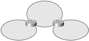
OSPF is a hierarchical routing protocol that breaks a network into areas. All OSPF areas must be connected to the backbone area (Area 0). The entire OSPF network is called the OSPF domain. Figure 7.1 illustrates a simple OSPF network.
F I G U R E 7 . 1 A simple OSPF network
Area 0
“Backbone” area
Area 1 |
Area 2 |
Notice in Figure 7.1 that the network is divided into three areas: Area 0, Area 1, and Area 2. Area 1 and Area 2 are connected to Area 0, which is the OSPF backbone. For now, just remember that in standard OSPF, all the areas must be connected to Area 0.
OSPF Router Types
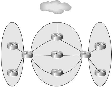
There are several OSPF router types that you need to be familiar with. Refer to Figure 7.2 as I explain each of these OSPF router types.
Backbone router In OSPF, Area 0 is the backbone area. Any router that has an interface configured for Area 0 is called a backbone router.
Internal router Any router that has all its interfaces configured for a single area is said to be an internal router.
Area border router (ABR) An area border router (ABR) is a router that has interfaces configured for two or more areas. For example, a router with Serial 0/0 in Area 0 and Serial 0/1 in Area 1 is an ABR.
Autonomous system boundary router (ASBR) An autonomous system boundary router (ASBR) is a router that has at least one interface in the OSPF domain and one interface connecting to an external network. An example of an external network might be a connection to another AS running RIP.
Copyright ©2002 SYBEX, Inc., Alameda, CA |
www.sybex.com |
264 Chapter 7 MPLS VPNs and OSPF
F I G U R E 7 . 2 An OSPF network with router types
External AS
|
|
Backbone |
|
|
Internal |
|
router/ |
|
Internal |
router |
|
ASBR |
|
router |
|
|
R1 |
|
|
R6 |
ABR |
Internal backbone router |
ABR |
R8 |
|
|
|
||
Internal |
R4 |
R2 |
R5 |
Internal |
|
Internal backbone router |
|
||
router |
|
|
router |
|
R7 |
|
R3 |
|
R9 |
Area 1 |
|
Area 0 |
|
Area 2 |
As you may have already noticed in Figure 7.2, some routers can be more than one router type. To eliminate any confusion with these terms, I’ll describe each router illustrated in Figure 7.2 and discuss its type(s).
R1: Backbone router/ASBR R1 has a total of three interfaces. Two interfaces are in Area 0, making R1 a backbone router. R1 has a third interface that’s connected to an external AS, making it also an ASBR. Since all of R1’s interfaces are not in a single area, R1 is not an internal router.
R2: Internal router/backbone router R2 has two interfaces. Both of R2’s interfaces are in Area 0, making it a backbone router. Since both interfaces are in the same area, R2 is also an internal router.
R3: Internal router/backbone router R3 has two interfaces. Both of R3’s interfaces are in Area 0, making it a backbone router. Since both interfaces are in the same area, R3 is also an internal router.
R4: Backbone router/ABR R4 has two interfaces. One interface connects to Area 0, making R4 a backbone router. The second interface connects to a different area, making R4 an ABR.
Copyright ©2002 SYBEX, Inc., Alameda, CA |
www.sybex.com |

MP-BGP and OSPF 265
R5: Backbone router/ABR R5 has two interfaces. One interface connects to Area 0, making R5 a backbone router. The second interface connects to a different area, making R5 also an ABR.
R6: Internal router R6 has two interfaces. Both of R6’s interfaces are in Area 1, making R6 an internal router.
R7: Internal router R7 has two interfaces. Both of R7’s interfaces are in Area 1, making it an internal router.
R8: Internal router R8 has two interfaces. Both of R8’s interfaces are in Area 2, making R8 an internal router.
R9: Internal router R9 has two interfaces. Both of R9’s interfaces are in Area 2, making R9 an internal router.
Link State Advertisements
OSPF uses link state advertisements (LSAs) to exchange routing information between other OSPF-enabled routers. Table 7.1 lists the five main types of LSAs that will be discussed in this chapter.
T A B L E 7 . 1 OSPF LSA Types
LSA Type |
Advertisement |
Description |
|
|
|
1 |
Router LSA |
Router LSAs are only flooded in the area that |
|
|
they originate in. They contain information |
|
|
about the router and its directly connected links. |
2 |
Network LSA |
Network LSAs are generated by a designated |
|
|
router (DR) and are flooded only in the area |
|
|
that they originate in. They contain information |
|
|
about the routers that are connected to a multi- |
|
|
access network. |
3 |
Summary LSA |
Summary LSAs are generated by ABRs, and |
|
|
they contain information about networks from |
|
|
outside the area. For example, a Type 1 or Type 2 |
LSA will be advertised as a Type 3 LSA by an ABR and is flooded throughout the OSPF domain.
Copyright ©2002 SYBEX, Inc., Alameda, CA |
www.sybex.com |

266 Chapter 7 MPLS VPNs and OSPF
T A B L E 7 . 1 OSPF LSA Types (continued)
LSA Type |
Advertisement |
Description |
|
|
|
4 |
ASBR summary |
ASBR summary LSAs are generated by ABRs, |
|
LSA |
and they contain information about ASBRs from |
|
|
outside the area. |
5 |
External LSA |
External LSAs are generated by ASBRs, and they |
|
|
contain information about networks from out- |
|
|
side the OSPF domain. External LSAs are |
|
|
flooded throughout the OSPF domain. |
|
|
|
To help you understand the important LSA types, let’s look at two examples. In Figure 7.3, the router R5 generates an LSA Type 1 or Type 2. Once the update is received on R3, the ABR/ASBR, it is forwarded across the backbone area as a Type 3 LSA. When this Type 3 LSA is received by R2, an ABR, it is forwarded into Area 1 as a Type 3 LSA. The moral of the story is that Type 1 or Type 2 LSAs are only used inside a single area. They are forwarded to other areas as Type 3 LSAs.
F I G U R E 7 . 3 Type 1 or Type 2 updates
External AS
|
|
R2 |
|
R3 |
||
|
|
|
|
|
|
|
R4 |
R1 |
|
R5 |
|||
|
|
|
|
|
||
LSA Type 3 |
LSA Type 3 |
|
LSA Type 1 |
|||
|
|
|
|
|
or Type 2 |
|
Area 1 |
Area 0 |
|
Area 2 |
|||
In Figure 7.4, an external route is learned by R3, an ABR/ASBR, and an LSA Type 5 is generated. Notice that the update is flooded throughout the OSPF network as a Type 5, or external LSA.
Copyright ©2002 SYBEX, Inc., Alameda, CA |
www.sybex.com |