

Answers to Review Questions 91
Answers to Review Questions
1.C. MPLS and tag switching will not work without CEF. The command to enable CEF in global configuration mode is ip cef.
2.B. The command to enable MPLS in global configuration mode is mpls ip.
3.B. The command to enable MPLS on an interface is mpls ip. The mpls ip command is not only used to configure MPLS globally; it’s also used to configure MPLS on an interface.
4.C. To enable tag switching globally, use the tag-switching advertise-tags command.
5.D. To enable tag switching on an interface, use the tag-switching ip command.
6.B. To view TDP neighbors, use the show tag-switching tdp neighbor command.
7.B. To view LDP neighbors, use the show mpls ldp neighbor command.
8.C. Tag switching uses TDP to exchange labels between neighbors.
9.B. MPLS uses LDP to exchange labels between neighbors.
10.B. Frame-mode MPLS label distribution can be described as independent control with unsolicited downstream. Independent control means immediately bind a label to an FEC. Unsolicited downstream means to advertise the new binding without waiting for the neighbors to send a request.
11.A. ATM-LSRs wait on labels from a downstream LSR. This method is called ordered control.
12.D. TDP uses TCP port 711 to exchange tags with a peer after a neighbor has been discovered.
13.B. LDP uses TCP port 646 to exchange labels with a peer after a neighbor has been discovered.
14.D. Packets enter the network as unlabeled IP. The PE, or edge-LSR, imposes labels on packets.
Copyright ©2002 SYBEX, Inc., Alameda, CA |
www.sybex.com |
92Chapter 2 Frame-Mode MPLS
15.A. Customer devices do not need MPLS functionality to connect to an MPLS-enabled service provider network.
16.C. Packets enter the network at an ingress router and exit the network at the egress router.
17.B. LSRs label-switch packets. If an unlabeled packet is received, the LSR performs a Layer 3 lookup on the packet.
18.D. The LDP/TDP identifier is first based on the highest IP address of the configured loopback interfaces. If there are no loopbacks, the highest IP address of the active interfaces is used.
19.D. MPLS in an ATM environment and cell-mode MPLS use ordered control with downstream-on-demand.
20.C. You can run both protocols on the same LSR, which is useful for migrations from a TDP to an LDP environment, but LDP and TDP are not compatible. For neighbors to exchange labels, the interface they communicate over must run the same protocol.
Copyright ©2002 SYBEX, Inc., Alameda, CA |
www.sybex.com |

Chapter
3
MPLS and ATM
CCIP MPLS EXAM TOPICS COVERED IN THIS CHAPTER:
Describe frame-mode MPLS and cell-mode MPLS.
Describe the loop-detection and prevention mechanisms in MPLS.
Identify the IOS commands and their proper syntax used to configure frame-mode MPLS on ATM PVC on IOS platforms.
Identify the IOS commands and their proper syntax used to configure cell-mode MPLS on ATM interfaces on IOS platforms.
Identify the IOS commands and their proper syntax used to monitor operations and troubleshoot typical cell-mode MPLS failures on IOS platforms.
Copyright ©2002 SYBEX, Inc., Alameda, CA |
www.sybex.com |

In Chapter 2, “Frame-Mode MPLS,” you learned how framemode MPLS operates and how it is configured in Cisco IOS routers. This chapter discusses frame-mode MPLS in an ATM network. In particular, you’ll learn how frame-mode MPLS is implemented across non-MPLS- enabled routers and how to configure a PE router for frame-mode MPLS across an ATM link.
In this chapter, you’ll also learn about cell-mode MPLS, what is required to turn non-MPLS ATM switches into ATM-LSRs, and how cell-mode devices forward labeled packets across the network.
This is the last chapter in the book that discusses generic MPLS operation. After this chapter, it’ll be VPNs from here on out.
Frame-Mode MPLS and ATM
The biggest difference between frame-mode and cell-mode MPLS is in how the MPLS control plane in ATM works. The control plane of the MPLS architecture is responsible for binding a label to network routes and distributing those bindings among other MPLS-enabled routers. Remember the statement, “Labels are bound to routes in the routing table.” In frame-mode
MPLS, routers are directly connected across frame-mode interfaces such as PPP. Routers, with frame-mode MPLS enabled, use pure IP to exchange information such as label bindings and routing table updates.
One of the requirements for MPLS is that control-plane information be
exchanged using pure unlabeled IP.
Copyright ©2002 SYBEX, Inc., Alameda, CA |
www.sybex.com |
Frame-Mode MPLS and ATM 95
ATM switches don’t have any direct interfaces to use for the exchange of IP-based control-plane communication, so a virtual circuit (VC) must be configured between LSRs.
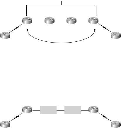
Recall that Chapter 2 used the simple router-based service provider network illustrated in Figure 3.1.
F I G U R E 3 . 1 A simple router-based service provider network
IGP
|
Serial |
0/0 |
0/0 |
Serial |
0/1 |
0/0 |
Serial |
0/1 |
0/0 |
|
Serial 0/1 |
Serial |
|
Serial |
|
Serial |
|
Serial 0/1 |
|||
|
|
|
|
|
|
|
|
|
||
PE1 |
|
P1 |
|
|
P2 |
|
|
PE2 |
||
Serial 0 |
|
|
|
|
|
|
|
|
Serial 0 |
|
CE1 |
|
|
|
|
|
|
|
|
CE2 |
|
|
|
|
|
I-BGP |
|
|
|
|
|
|
In Figure 3.1, all the network devices are connected together through frame-based interfaces. In the case of Figure 3.1, given that serial interfaces are shown, either Cisco’s High-Level Data Link Control (HDLC) or Point- to-Point Protocol (PPP) encapsulation is supported. Either way, these are frame-mode interfaces. With frame-mode interfaces, routers exchange controlplane information such as label bindings and routing updates directly.
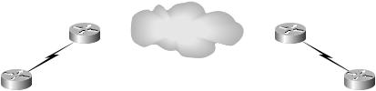
In Figure 3.2, the core routers (P1 and P2) have been replaced with nonMPLS ATM switches.
F I G U R E 3 . 2 A simple service provider network with an ATM core
PE1 |
ATM |
|
ATM |
PE2 |
|
|
|
||
|
|
|||
CE1 |
|
|
CE2 |
|
Remember that control-plane traffic must take place with unlabeled IP packets. How can MPLS be implemented in the network shown in Figure 3.2? With a permanent virtual circuit (PVC) between the edge-LSRs. In Figure 3.3, a PVC has been set up between PE1 and PE2.
Copyright ©2002 SYBEX, Inc., Alameda, CA |
www.sybex.com |
96 Chapter 3 MPLS and ATM
F I G U R E 3 . 3 Edge-LSRs connected with a PVC
|
|
PVC |
|
PE1 |
PE2 |
||
CE1 |
|
CE2 |
|
Let’s talk about Figure 3.3 without adding MPLS to the network. Suppose a user on CE1 wants to send data to a user on CE2. When a packet arrives from CE1 on PE1, it is an unlabeled IP packet (no MPLS yet). PE1 examines the packet and makes a forwarding decision (no MPLS deployed yet). In Figure 3.3, to get a packet to CE2, it must be forwarded to PE2. The packet is placed in the PVC and traverses the ATM core until it arrives at PE2 (still no MPLS). PE2 examines the packet and forwards it to CE2.
Now that you’ve seen the network without MPLS, let’s talk about the network with MPLS. To start with, PE1 and PE2 are MPLS-capable routers with ATM interfaces. PE1 and PE2 are edge-LSRs. In addition, PE1 and PE2 can be called ATM edge-LSRs.
Let me explain ATM edge-LSRs. A label switch router (LSR) is a Cisco IOS router/switch that is capable of forwarding packets based on labels. An edge label switch router (edge-LSR) is a more specific term for the PE routers that sit at the edge of the service provider network. An ATM edge-LSR is an edge-LSR with at least one ATM interface.
As you can see in Figure 3.3, the ATM network is shown as a cloud with a PVC connecting PE1 and PE2. The ATM switches use virtual path identifier (VPI) and virtual channel identifier (VCI) mappings to create the PVC. The ATM switches do not examine the packets they are transporting; they only switch them based on the VPI/VCI values.
The routers, being IP devices, simply place packets on the PVC, and the
ATM network does the rest. PE1 and PE2, connected by a PVC, exchange MPLS control-plane information with pure IP packets.
So, with MPLS enabled, the network operates similarly to what you saw in Chapter 2. For example, suppose a user on CE1 wants to send data to a user on CE2. CE1 sends an unlabeled IP packet to PE1. PE1 receives the packet and forwards it to PE2. In the network in Figure 3.3, PE1 does not apply a label to the packet (remember penultimate hop popping). Instead, PE1 forwards the packet as unlabeled IP to PE2 as the next hop. If there was
Copyright ©2002 SYBEX, Inc., Alameda, CA |
www.sybex.com |