

100 Chapter 3 MPLS and ATM
192.168.1.2:0
TCP connection: 192.168.1.1:11004 - 192.168.1.2.678 State: Oper; PIEs sent/rcvd: 1506/1500; ; Downstream Up time: 12:36:08
TDP discovery sources: ATM1/0.1
Addresses bound to peer TDP Ident: 192.168.1.10 192.168.1.1
Cell-Mode MPLS
First of all, most ATM switches don’t support MPLS without a little modification. For MPLS to work on ATM switches, they must be upgraded to ATM-LSRs.
An ATM label switch router (ATM-LSR) is an ATM switch that is capable of forwarding packets based on labels. Cisco ATM switches such as the LightStream 1010 support MPLS without any modification. If MPLS functionality is not native on the switch, a controller card is required to implement MPLS. For example, when an external label switch controller (LSC) is added to the switch, the LSC can exchange routes and labels with its neighbors. The LSC communicates with the ATM switch using VC 0/32.
Now that an ATM switch is an ATM-LSR, it supports two different signaling protocols running simultaneously in a ships-passing-in-the-night fashion. For MPLS, LDP is running. For ATM, UNI and PNNI are running. These signaling protocols run side by side, but they don’t communicate directly with each other.
If you are not an ATM guru, let me explain what all this means. Let’s go back to frame-mode MPLS for a minute. A label was applied by the ingress edge-LSR and then label-switched across the service provider network. The LSRs in the service provider core did not look at the Layer 3 information; instead, they only examined the label.
Well, ATM switches can’t examine labels; they must switch traffic based only on VPI/VCI values. Therefore, for ATM, the label is mapped to the VPI/ VCI values. In essence, the label replaces the VPI/VCI value. The process of an unlabeled IP packet entering the network, having a label imposed, and then being label-switched has not changed. The only thing that’s different is that in ATM, the label is the VPI/VCI value.
Copyright ©2002 SYBEX, Inc., Alameda, CA |
www.sybex.com |

Cell-Mode MPLS 101
Label Binding with ATM
If you aren’t already familiar with ATM, label binding can get a little confusing. I’ll explain what you need to know for the exam so you don’t have to spend the next year learning all about ATM.
To really understand how MPLS works in an ATM environment, let’s start with how labels get bound. MPLS in an ATM network uses ordered control with downstream-on-demand.
Ordered control Ordered control occurs when an upstream LSR must wait for a label to be received from its downstream LSR. Ordered control takes longer to set up a label-switched path (LSP) and is used by MPLSenabled ATM switches (ATM-LSRs).
Downstream-on-demand Downstream-on-demand occurs when an upstream LSR, using the Label Request message, requests a label from its downstream neighbor.
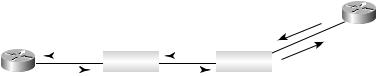
Figure 3.5 illustrates a service provider network with two POP locations (Melbourne and Ft. Lauderdale) connected together with two ATM-LSRs (Orlando_ATM and Miami_ATM).
F I G U R E 3 . 5 A service provider network with ATM-LSRs
|
ATM |
|
ATM |
|
192.168.1.0 |
Melbourne POP |
|
|
|
Ft. Lauderdale POP |
|
Orlando_ATM |
Miami_ATM |
||||
Upstream |
|
|
|
Downstream |
|
Before discussing about how labels get allocated, let’s first identify what is meant by upstream and what is meant by downstream. In Figure 3.5, the network 192.168.1.0 is being advertised from the Ft. Lauderdale POP router. Eventually, through the routing protocol used in the service provider core, the route will be learned by the Melbourne POP router. So traffic coming from the Melbourne POP going to the Ft. Lauderdale POP moves from left to right. The Melbourne POP router is upstream and the Ft. Lauderdale POP is downstream.
MPLS in an ATM network uses ordered control with downstream-on- demand. It’s also true that cell-mode MPLS operates though ordered control and downstream-on-demand.
When exactly does ordered control occur? Ordered control occurs when an upstream LSR, in this case the Melbourne POP router, must wait for a
Copyright ©2002 SYBEX, Inc., Alameda, CA |
www.sybex.com |
102 Chapter 3 MPLS and ATM
label to be received from its downstream LSR (or in the case of Figure 3.5, its downstream ATM-LSR, the Orlando_ATM switch). All this means is that the Melbourne POP router does not create a label, but instead it waits to be told what label to use by the Orlando_ATM switch.
Downstream-on-demand occurs when an upstream LSR, in this case the Melbourne POP router using the Label Request message, requests a label from its downstream neighbor, the Orlando_ATM switch.
So how do labels get bound in the network shown in Figure 3.5? Using the most basic terminology, the Melbourne POP router needs to know the LSP between it and the Ft. Lauderdale POP. So the Melbourne POP router asks its neighbor, the Orlando_ATM switch, which label it should use. The Orlando_ATM switch asks the Miami_ATM switch. The Miami_ATM switch asks the Ft. Lauderdale POP router. The Ft. Lauderdale POP router tells the Miami_ATM switch, who tells the Orlando_ATM switch, who tells the Melbourne POP router which label to use, and in the case of ATM, which VPI/VCI values to use.
Now, let’s add a little detail. Figure 3.6 illustrates the label request and VPI/VCI mapping flow.
F I G U R E 3 . 6 A service provider network with label and VPI/VCI mappings
Ft. Lauderdale POP
|
|
|
|
|
|
|
|
|
|
|
|
VPI/VCI |
|
VPI/VCI |
VPI/VCI |
|
192.168.1.0 |
||||||||
|
|
Label |
||||||||||
|
|
|
|
|
ATM |
|
|
|
|
|
ATM |
|
|
|
|
|
|
|
|
|
|
|
|||
|
|
|
|
|
|
|
|
|
|
request |
||
|
|
|
|
|
|
|
|
|
|
|
|
|
Melbourne POP Label Orlando_ATM |
|
Label |
Miami_ATM |
|
||||||||
|
|
request |
request |
|
|
|||||||
As you read what happens between LSRs in an ATM environment, I want you to focus on the VPI/VCI mappings.
The Melbourne POP router sees a route in its routing table for the network 192.168.1.0. To send traffic to the network 192.168.1.0, the Melbourne POP router sends a request to its downstream ATM-LSR, Orlando_ATM, requesting a label for the network 192.168.1.0.
The Orlando_ATM switch, upon receiving the request, sends a request to its downstream ATM-LSR, Miami_ATM, requesting a label for the network 192.168.1.0. When the request arrives at the Miami_ATM switch, a request is sent to the Ft. Lauderdale POP router requesting a label for the network 192.168.1.0.
Copyright ©2002 SYBEX, Inc., Alameda, CA |
www.sybex.com |
Cell-Mode MPLS 103
At the Ft. Lauderdale POP router, two options exist for the network 192.168.1.0. Either the network 192.168.1.0 is reachable from a downstream ATM-LSR, or it needs to have the label popped (recall penultimate hop popping). A new label is allocated out of the pool of free VCs on the LCATM interface. This new label is added to the label forwarding information base (LFIB) with the associated VPI/VCI pair. The new VPI/VCI pair is sent back to the Miami_ATM switch through either TDP or LDP.
An LC-ATM is a label-switching controlled ATM interface where the VPI/VCI is
assigned through MPLS or tag switching (LDP or TDP).
At the Miami_ATM switch, a new label is allocated out of the pool of free VCs on the LC-ATM interface. A mapping between the outgoing VPI/VCI (from the Ft. Lauderdale POP router) and the incoming VPI/VCI (that is going to be sent to the Orlando_ATM switch) is created. The new VPI/VCI pair is sent back to the Orlando_ATM switch.
At the Orlando_ATM switch, a new label is allocated out of the pool of free VCs on the LC-ATM interface. A mapping between the outgoing VPI/ VCI (from the Miami_ATM switch) and the incoming VPI/VCI (that is going to be sent to the Melbourne POP router) is created. The new VPI/VCI pair is sent back to the Melbourne POP router.
The important information to get out of all of this is that labels are being assigned and mapped to VPI/VCI pairs.
Cell-Mode Label Switching
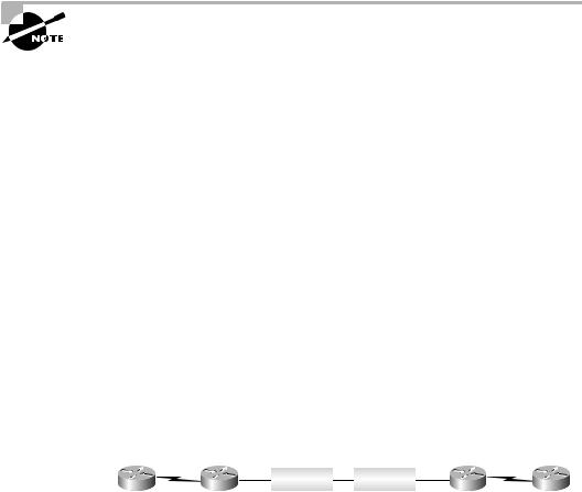
This section uses the simple service provider network illustrated in Figure 3.7 to explain how cell-mode label switching works across an ATM-LSR network.
F I G U R E 3 . 7 A cell-mode service provider network
|
|
ATM |
|
ATM |
|
|
|
|
|
|
|
|
|
Site 1 |
Melbourne POP Orlando_ATM |
Miami_ATM Ft. Lauderdale POP |
Site 2 |
|||
Table 3.1 lists the role of each device in the network in Figure 3.7.
Copyright ©2002 SYBEX, Inc., Alameda, CA |
www.sybex.com |