

- •Acknowledgments
- •Introduction
- •Assessment Test
- •Answers to Assessment Test
- •Service Provider Networks
- •Scalability
- •Traffic Engineering
- •Quality of Service
- •MPLS Label Stack
- •Shim Header
- •MPLS Architecture
- •Control
- •Forwarding
- •MPLS Label Switching
- •MPLS Network Components
- •Device Output
- •Label-Switched Paths
- •MPLS Applications
- •MPLS and ATM
- •Overlay
- •Quality of Service
- •Traffic Engineering
- •Summary
- •Exam Essentials
- •Key Terms
- •Review Questions
- •Answers to Review Questions
- •Routing Review
- •Frame-Mode MPLS Working Example
- •Network Routing Protocol Examples
- •MPLS Step by Step
- •Label Distribution
- •Assigning Labels
- •Troubleshooting and Verification
- •Device Configuration
- •IGP Verification
- •CEF Verification
- •MPLS Verification
- •Label Distribution and Bindings
- •Binding Verification
- •Troubleshooting the Network
- •Hiding Service Provider Devices
- •Summary
- •Exam Essentials
- •Key Terms
- •Review Questions
- •Answers to Review Questions
- •Frame-Mode MPLS and ATM
- •Frame-Mode MPLS and ATM Configuration
- •Cell-Mode MPLS
- •Label Binding with ATM
- •Cell-Mode Label Switching
- •VC Merge
- •Loop Prevention
- •Cell-Mode MPLS Configuration
- •Summary
- •Exam Essentials
- •Key Terms
- •Review Questions
- •Answers to Review Questions
- •VPNs 101
- •Point-to-Point Connections
- •Virtual Private Networks
- •Categories of VPNs
- •VPN Routing
- •Peer-to-Peer VPNs
- •Optimal Routing
- •Peer-to-Peer Security
- •Peer-to-Peer VPN Routing
- •Summary
- •Exam Essentials
- •Key Terms
- •Review Questions
- •Answers to Review Questions
- •Service Provider Configuration
- •MPLS VPNs
- •Virtual Router
- •Virtual Routing and Forwarding Tables
- •MPLS Operational Overview
- •MP-BGP Configuration
- •An MPLS VPN Example
- •Route Distinguisher
- •MP-IBGP Configuration Example
- •Initial Network Configuration
- •MP-IBGP Configuration
- •Verification
- •Summary
- •Exam Essentials
- •Key Terms
- •Review Questions
- •Answers to Review Questions
- •A Review of VPNs
- •Configuring a Simple MPLS VPN
- •Configuring VRF Interfaces
- •Running RIP in an MPLS VPN
- •Configuring RIPv2 with Address-Family ipv4
- •Configuring Redistribution
- •Route Targets
- •Configuring Route Targets
- •A Review of Simple VPN Configuration
- •Configuring MPLS in the Service Provider Network
- •Simple VPN Configuration
- •Configuring the PE-CE Routing Protocol
- •Lab: Configuring an MPLS VPN
- •Configuring POP Routers
- •VPN Configuration
- •Raleigh Running-Config
- •Atlanta Running-Config
- •Peer 1 Running-Config
- •Peer 2 Running-Config
- •Verification with Ping
- •Routing Table Isolation
- •Verifying VRF Routes
- •Summary
- •Exam Essentials
- •Key Terms
- •Review Questions
- •Answers to Review Questions
- •MP-BGP and OSPF
- •A Review of OSPF
- •OSPF Router Types
- •Link State Advertisements
- •OSPF for MPLS VPNs
- •OSPF Super-Backbone
- •Preventing Routing Loops
- •Path Selection
- •MPLS VPN OSPF Lab
- •Summary
- •Exam Essentials
- •Key Terms
- •Review Questions
- •Answers to Review Questions
- •Static Routing
- •Device Configuration
- •VPN Configuration
- •Raleigh Running-Config
- •Atlanta Running-Config
- •Peer Router Configuration
- •Verification with Ping
- •Verifying Static VRF Routes
- •E-BGP and MPLS VPNs
- •Device Configuration
- •E-BGP Operation
- •AS-Override
- •VPN Configuration
- •Raleigh Running-Config
- •Atlanta Running-Config
- •Peer Router Configuration
- •Peer 1 Running-Config
- •Peer 2 Running-Config
- •Verification with Ping
- •Advanced MPLS VPN Topologies
- •Simple VPNs
- •Central Services MPLS VPN Topology
- •Overlay MPLS VPN Topology
- •Summary
- •Exam Essentials
- •Key Terms
- •Review Questions
- •Answers to Review Questions
- •Challenge Lab 1
- •MPLS
- •MP-IBGP
- •Answer to Lab 1.1
- •Answer to Lab 1.2
- •Answer to Lab 1.3
- •Challenge Lab 2
- •Tag Switching
- •MP-IBGP
- •Answer to Lab 2.1
- •Answer to Lab 2.2
- •Answer to Lab 2.3
- •Challenge Lab 3
- •VRF Configuration
- •RIPv2
- •Redistribution
- •Answer to Lab 3.1
- •Answer to Lab 3.2
- •Answer to Lab 3.3
- •Challenge Lab 4
- •VRF Configuration
- •OSPF
- •Redistribution
- •Answer to Lab 4.1
- •Answer to Lab 4.2
- •Answer to Lab 4.3
- •Challenge Lab 5
- •VRF Configuration
- •Static Routes and Redistribution
- •Answer to Lab 5.1
- •Answer to Lab 5.2
- •Challenge Lab 6
- •VRF Configuration
- •E-BGP Configuration
- •Answer to Lab 6.1
- •Answer to Lab 6.2
- •Service Provider Network Configuration with OSPF
- •Router Configuration
- •Routing Tables
- •Tags
- •Service Provider Network Configuration with IS-IS
- •Router Configuration
- •Routing Tables
- •Tag Switching Forwarding Tables
- •Glossary

MP-BGP and OSPF 267
F I G U R E 7 . 4 Flooding of LSA Type 5
External AS
|
|
|
|
|
External |
|
|
|
|
|
|
route |
|
|
|
R2 |
|
R3 |
||
|
|
|
|
|
|
|
R4 |
R1 |
|
R5 |
|||
|
|
|
|
|
||
LSA Type 5 |
LSA Type 5 |
|
LSA Type 5 |
|||
Area 1 |
Area 0 |
|
Area 2 |
|||
There are two types of external routes (Type 5): E1 and E2. The default for Cisco devices is E2.
OSPF for MPLS VPNs
Whenever an MPLS VPN is established, the service provider is inserted between the customer sites. For example, Figure 7.5 illustrates a simple twosite OSPF network connected together with Frame Relay.
F I G U R E 7 . 5 A two-site OSPF network
OSPF domain
Area 0
|
Frame Relay |
Site 1 |
VC1 |
Site 2 |
When the service provider is inserted between the two customer sites,
OSPF routes must be redistributed from OSPF into BGP, and then back into
Copyright ©2002 SYBEX, Inc., Alameda, CA |
www.sybex.com |
268 Chapter 7 MPLS VPNs and OSPF
OSPF. As you can see in Figure 7.6, an OSPF from Site 1 traverses the service provider network as a BGP route. For the route to be sent to Site 2, the BGP route must be redistributed back into OSPF.
F I G U R E |
7 . 6 |
OSPF-to-BGP redistribution |
|
|
|
|
|||||
|
|
Site 1 |
PE1 |
PE2 |
|
Site 2 |
|||||
|
|
|
|
|
|
|
|
|
|
|
|
|
|
|
|
OSPF |
|
|
|
OSPF |
|||
|
|
LSA Type 1 or Type 2 |
|
BGP |
|
LSA Type 5 |
|||||
|
|
|
|
|
|
|
|
|
|
|
|
|
|
|
|
OSPF Area 0 |
|
BGP |
|
OSPF Area 0 |
|||
|
|
There’s a “gotcha” here that needs a little explaining. Figure 7.7 illus- |
|||||||||
|
|
trates a simple two-site OSPF network connected with Frame Relay. |
|||||||||
F I G U R E |
7 . 7 |
A two-site OSPF network with addresses |
|
|
|
|
|||||
|
|
|
|
|
|
|
OSPF domain |
|
|
|
|
|
|
|
|
|
|
|
Area 0 |
|
|
|
|
10.1.0.0/16
Ethernet0 |
Serial |
0 |
Site 1
Frame Relay
VC1
10.3.0.0/16
0 |
Ethernet0 |
Serial |
|
|
Site 2 |
10.2.0.0/16
In Figure 7.7, the network 10.1.0.0/16 shows up as connected (C) in the routing table on the Site 1 router. When network 10.1.0.0/16 is learned by Site 2, it shows up as (O) in the routing table. The reason for this is that both Site 1 and Site 2 are in the same area (Area 0). Routes that are from the internal area show up as (O) in the routing table.
Now let’s take a look at what happens when the service provider is introduced into the picture. Figure 7.8 shows a customer OSPF network separated by a service provider BGP network. OSPF routes from both Site 1 and Site 2 must be redistributed into BGP to traverse the service provider network. Since both PE1 and PE2 are connected to an OSPF area and to an external autonomous system (the service provider BGP backbone), they can be called ASBRs. Remember that routes from external autonomous systems are advertised into OSPF as Type 5 LSAs.
Copyright ©2002 SYBEX, Inc., Alameda, CA |
www.sybex.com |

MP-BGP and OSPF 269
The Cisco IOS default is to mark the external route as (O E2) or as an OSPF external Type 2 route. So, what does this mean? Well, the 10.1.0.0/16 network advertisement from Site 1 shows up as an external route (O E2) instead of as an internal route (O) at Site 2. Conversely, the 10.2.0.0/16 network advertisement from Site 2 shows up as an external route (O E2) instead of as an internal route (O) at Site 1.
F I G U R E 7 . 8 OSPF-to-BGP redistribution with addresses
10.1.0.0/16
Site 1 |
PE1 |
PE2 |
Site 2 |
|
||
ASBR |
ASBR |
|
||||
|
|
|
Service provider |
|
|
|
|
|
|
|
|
|
|
|
|
OSPF Area 0 |
BGP |
OSPF Area 0 |
|
|
|
|
|
||||
10.2.0.0/16
No big deal, right? Wrong! In Figure 7.8, everything works fine. The problem that you’ll encounter is when an alternate connection exists between the two sites. In Figure 7.9, Site 1 and Site 2 are connected to the service provider. In addition, they have an alternate connection through Frame Relay just in case the service provider network is unavailable.
F I G U R E 7 . 9 OSPF network with an alternate connection
|
|
BGP |
|
|
PE1 |
Service |
PE2 |
|
|
|
|
|
|
provider |
|
|
|
network |
|
10.1.0.0/16 |
Area 0 |
|
Area 0 |
Area 0 |
VC1 |
Area 0 |
|
|
Site 1 |
|
Site 2 |
|
|
Frame Relay |
|
10.2.0.0/16
The gotcha is that internal (O) routes are always preferred over external (O E2) routes. Let me explain. Site 1 generates an OSPF route for the network 10.1.0.0/16. The OSPF route is redistributed into BGP and arrives at Site 2 as an external route (O E2). In addition, Site 2 learns of the route through OSPF across the alternate Frame Relay connection, resulting in an internal route (O) in the routing table. Since the primary connection is through the service provider and the alternate connection is there just in case, it’s safe to
Copyright ©2002 SYBEX, Inc., Alameda, CA |
www.sybex.com |

270 Chapter 7 MPLS VPNs and OSPF
assume that the service provider connection is the fastest. Which way do you want the traffic to travel? Through the fastest connection, which is the service provider network. Here’s the gotcha: Since internal routes (O) are preferred over external routes (O E2), the connection through the alternate connection is preferred, and traffic will always flow from Site 1 to Site 2 across the alternate Frame Relay connection as long as it is available.
To get around this problem in MPLS VPNs, a solution called the OSPF super-backbone was introduced.
OSPF Super-Backbone
In the OSPF hierarchy, all areas had to connect directly to the backbone area
(Area 0). The MP-IBGP backbone, functioning as the super-backbone, replaces the Area 0 requirement, meaning that all areas connect to the superbackbone instead of to the Area 0 backbone. Without the super-backbone,
PE routers appear as ASBRs. Now, with the super-backbone, PE routers appear as ABRs. Remember that ASBRs advertise LSA Type 5 routes and ABRs advertise LSA Type 3 routes.
Nothing is better than illustrations when explaining all of this. In Figure 7.10, an OSPF network is separated by the service provider’s standard BGP backbone. LSA Type 1 or Type 2 routes from Site 1 are redistributed into BGP by a service provider router (PE1) that appears as an ASBR. PE2, an ASBR, redistributes the route from Site 1 back into OSPF and advertises it to Site 2 as an LSA Type 5.
F I G U R E 7 . 1 0 OSPF and standard BGP interaction
Site 1 |
PE1 |
|
PE2 |
|
Site 2 |
||
ASBR |
|
ASBR |
|
||||
|
|
|
|
Service |
|
|
|
|
|
|
|
provider network |
|
|
|
LSA Type 1 or Type 2 |
|
BGP |
LSA Type 5 |
||||
|
|
|
|
|
|
|
|
|
OSPF Area 0 |
|
BGP |
OSPF Area 0 |
|||
Figure 7.11 illustrates the interaction between standard OSPF and the OSPF super-backbone.
Notice in Figure 7.11 that both PE1 and PE2 appear as ABRs. LSA Type 1 or Type 2 routes from Site 1 are redistributed into BGP by a service provider router (PE1) that appears as an ABR. PE2, an ABR, redistributes the route from Site 1 back into OSPF and advertises it to Site 2 as an LSA Type 3.
Copyright ©2002 SYBEX, Inc., Alameda, CA |
www.sybex.com |

MP-BGP and OSPF 271
LSA Type 3 routes are inter-area routes and are displayed as Type O IA in the routing table.
F I G U R E 7 . 1 1 OSPF and OSPF super-backbone interaction
Site 1 |
PE1 |
PE2 |
|
Site 2 |
||
ABR |
ABR |
|
||||
|
|
|
|
Service |
|
|
|
|
|
|
provider network |
|
|
LSA Type 1 or Type 2 |
|
|
LSA Type 3 |
|||
|
|
|
|
|
|
|
|
OSPF Area 0 |
|
Super-backbone |
OSPF Area 0 |
||
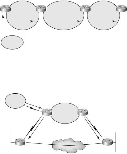
Where the OSPF super-backbone becomes really important is when there are alternate connections between customer sites. In Figure 7.12, two sites are connected through the OSPF super-backbone and an alternate internal OSPF connection. From Site 1, network 10.1.0.0/16 is advertised to PE1 and Site 2 through the alternate connection. The route, received by PE1, will be received by Site 2 as an inter-area route (O IA). The route received from Site 1 across the alternate connection is an internal route (O).
F I G U R E 7 . 1 2 An alternate connection with super-backbone
|
|
|
|
|
|
|
|
|
|
|
Super-backbone |
|
|
|
|
|
|
|
|
|
|
|
|
|
PE1 |
Service |
PE2 |
||
|
|
|
|
|
|
|
|
2 |
|
|
LSA |
|||
|
|
|
|
|
|
|
Type |
|
|
provider |
||||
|
|
|
|
|
|
|
|
|
|
|
|
|
||
|
Area 0 |
|
|
or |
|
|
|
network |
Type |
|||||
|
Type |
1 |
|
|
|
3 |
|
1 Area 0 |
||||||
|
|
|
|
|
|
|
|
|
|
Type |
||||
|
|
|
|
|
|
|
|
|
|
|
|
or |
||
|
|
|
|
|
|
|
|
|
Type |
|
|
LSA |
||
|
|
LSA |
|
|
|
LSA |
|
|
Type |
|||||
|
|
|
|
|
|
|
|
|
|
2 |
|
|||
10.1.0.0/16 |
Site 1 |
|
|
|
Area 0 |
|
VC1 |
3 |
|
|
||||
|
|
|
|
Area 0 |
||||||||||
|
|
|
|
|
|
|
|
|
|
Site 2 |
||||
|
|
|
|
|
|
|
|
|
|
|
Frame Relay |
|
|
|
|
|
|
|
|
|
|
|
|
|
|
|
|
|
|
|
|
|
|
|
|
|
|
|
|
|
|
|
|
|
|
|
|
|
|
|
|
|
|
|
|
|
|
|
|
10.2.0.0/16
LSA Type 1 or Type 2
LSA Type 1 or Type 2
When a route is redistributed into BGP, the OSPF cost is carried in the MED.
Copyright ©2002 SYBEX, Inc., Alameda, CA |
www.sybex.com |
272 Chapter 7 MPLS VPNs and OSPF
The OSPF super-backbone is made possible by a new BGP extended community that carries the route type and area across the service provider’s BGP backbone. Since the route type is being carried in the extended community, an LSA Type 3 stays an LSA Type 3 and an LSA Type 5 stays a Type 5. In Figure 7.13, an external route is learned by Site 1 and is sent to PE1 as an external route (Type 5). PE1 redistributes the route into BGP and preserves the route type. When the route is redistributed into OSPF by PE2, the preserved route type (Type 5) results in Site 2 learning an external route (O E2).
F I G U R E 7 . 1 3 External route preservation
Site 1 |
|
PE1 |
|
PE2 |
|
Site 2 |
|||
|
|
|
|
|
|
|
|
|
|
Route |
|
|
LSA Type 5 |
BGP |
LSA Type 5 |
||||
|
|
||||||||
|
|
|
|
|
|
|
|
|
|
|
|
OSPF Area 0 |
Super-backbone |
OSPF Area 0 |
|||||
|
|
|
|||||||
|
|
|
|
|
|
|
|
|
|
|
|
|
|
|
|
|
|
|
|
External AS
In Figure 7.14, the external AS is connected to PE1. When routes from outside the OSPF domain are sent to Site 1 and Site 2, they are correctly sent as Type 5 routes (O E2).
F I G U R E 7 . 1 4 An external AS connected to a PE
External AS |
|
|
|
|
|
|
|
|
Route |
|
|
Super-backbone |
|
|
|
|
PE1 |
|
PE2 |
|
|
|
|
|
Service |
||
|
|
|
|
|
|
|
|
|
|
|
|
provider |
|
|
|
Area 0 |
|
|
network |
Area 0 |
|
|
|
|
|
||
|
|
|
Type |
5 |
|
LSA |
|
|
LSA |
|
|
Type |
|
10.1.0.0/16 |
Site 1 |
|
|
|
5 |
|
Area 0 |
|
VC1 |
||||
|
Area 0 |
|||||
|
|
|
|
|
|
|
|
|
|
|
|
Frame Relay |
|
Site 2
10.2.0.0/16
Copyright ©2002 SYBEX, Inc., Alameda, CA |
www.sybex.com |