

Frame-Mode MPLS Working Example 43
At each router between the host devices, the Layer 3 information is checked and a routing determination is made. If a route does not exist for a destination network and there is not a default route, the packet is dropped into the bottomless bit bucket of no return.
Frame-Mode MPLS Working Example
In Chapter 1, you learned about LSPs, penultimate hop popping, and the basics of MPLS. Frame-mode MPLS runs on routers with frame-mode interfaces. Frame-mode MPLS covers just about everything except Asynchronous Transfer Mode (ATM). This section uses the example service provider network illustrated in Figure 2.2 to build upon what you learned in
Chapter 1.
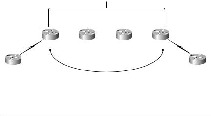
F I G U R E 2 . 2 A full service provider network
IGP
|
Serial |
0/0 |
0/0 |
0/1 |
0/0 |
Serial |
0/1 |
0/0 |
|
Serial 0/1 |
Serial |
|
Serial Serial |
|
Serial |
|
Serial 0/1 |
||
|
|
|
|
|
|
|
|
||
PE1 |
|
P1 |
|
P2 |
|
|
PE2 |
||
Serial 0 |
|
|
|
|
|
|
|
Serial 0 |
|
CE1 |
|
|
|
|
|
|
|
CE2 |
|
|
|
|
|
I-BGP |
|
|
|
|
|
Table 2.9 lists the IP addresses of the service provider devices in Figure 2.2.
T A B L E 2 . 9 Service Provider Network Device Addresses
Device |
Serial 0/0 |
Serial 0/1 |
Loopback 0 |
|
|
|
|
PE1 |
192.168.1.10 |
128.107.10.2 |
192.168.1.1 |
P1 |
192.168.1.9 |
192.168.1.14 |
192.168.1.2 |
P2 |
192.168.1.13 |
192.168.1.18 |
192.168.1.3 |
PE2 |
192.168.1.17 |
128.107.10.5 |
192.168.1.4 |
|
|
|
|
Copyright ©2002 SYBEX, Inc., Alameda, CA |
www.sybex.com |

44 Chapter 2 Frame-Mode MPLS
Table 2.10 lists the IP addresses of the customer devices in Figure 2.2.
T A B L E 2 . 1 0 Customer Device Addresses
Device |
Ethernet0 |
Serial 0 |
|
|
|
CE1 |
204.134.83.1 |
128.107.10.1 |
CE2 |
209.39.164.0 |
128.107.10.6 |
|
|
|
Network Routing Protocol Examples
The use of routing protocols by the devices in Figure 2.2 deserves a little discussion:
CE1 CE1 is configured with a default route out Serial 0 to the service provider network (PE1). CE1 is not an LSR.
PE1 PE1 is configured with a static route for network 204.134.83.0. PE1 is also configured with Border Gateway Protocol (BGP). An I-BGP session is configured between PE1 and PE2. For provider network routing, an Interior Gateway Protocol (IGP) is configured. For the purpose of this example, we’ll use the IGP Open Shortest Path First (OSPF). PE1 is an LSR.
BGP Configuration on Provider Edge Devices
If you are not familiar how BGP is going to be implemented, take a look at the configuration of PE1 and PE2. PE1 has the following BGP configuration:
router bgp 1
no synchronization
bgp log-neighbor-changes
network 192.168.1.1 mask 255.255.255.255
neighbor 192.168.1.4 remote-as 1
neighbor 192.168.1.4 update-source Loopback0
redistribute static
no auto-summary
Copyright ©2002 SYBEX, Inc., Alameda, CA |
www.sybex.com |

Frame-Mode MPLS Working Example 45
This configuration means that PE1 is advertising its loopback address (network 192.168.1.1, mask 255.255.255.255). PE1 has a neighbor, PE2, and they are part of the same autonomous system (neighbor 192.168.1.4, remoteas 1). Whenever PE1 communicates a route to its neighbor, Loopback 0 (192.168.1.1) of PE1 is used as the next hop address (neighbor 192.168.1.4, update-source Loopback 0). Statically entered routes are populated into BGP (redistribute static).
Based on this configuration, a static route is redistributed into BGP and sent to a neighbor router, with the next hop being the Loopback 0 of the originating router.
The configuration of PE2 is as follows:
router bgp 1
no synchronization
bgp log-neighbor-changes
network 192.168.1.4 mask 255.255.255.255
neighbor 192.168.1.1 remote-as 1
neighbor 192.168.1.1 update-source Loopback0
redistribute static
no auto-summary
The way that routes are communicated from PE2 to PE1 works the same way that routes are communicated from PE1 to PE2. On PE2, the loopback address (network 192.168.1.4, mask 255.255.255.255) is being advertised. PE2 has a neighbor of PE1, and they are part of the same autonomous system (neighbor 192.168.1.1, remote-as 1). Whenever PE1 communicates a route to its neighbor, the Loopback 0 (192.168.1.4) of PE1 is used as the next hop address (neighbor 192.168.1.1, update-source Loopback 0). Statically entered routes are populated into BGP (redistribute static).
P1 P1 is configured with OSPF for provider network routing. P1 is an LSR.
P2 P2 is configured with OSPF for provider network routing. P2 is an LSR.
PE2 PE2 is configured with a static route for network 209.39.164.0. PE1 is also configured with BGP. An I-BGP session is configured between PE1 and PE2. OSPF is configured as the service provider routing protocol. PE2 is an LSR.
Copyright ©2002 SYBEX, Inc., Alameda, CA |
www.sybex.com |

46 Chapter 2 Frame-Mode MPLS
CE2 CE2 is configured with a default route out Serial 0 to the service provider network (PE2). CE2 is not an LSR.
MPLS Step by Step
There is really no better way to learn MPLS than to see it in a step-by-step format. Take all the time you need to read through this section because the information you learn here will be used throughout this book.
Step 1 A host on the 204.134.83.0 subnet wants to send data to a host on the 209.39.164.0 subnet. The host knows that the destination host is remote and places a frame on the wire to its default gateway, which is CE1.
Step 2 Router CE1 receives the frame, discards the Layer 2 information, and does a Layer 3 lookup to see if it has a path to get to the destination network of 209.39.164.0. There is no route in the routing table for the destination network, so the packet is forwarded to PE1 using the default route or the gateway of last resort.
Step 3 Router PE1 receives the packet and does a Layer 3 lookup. PE1 knows about the destination network (it was learned from PE2 through BGP). The next hop address for the remote network is 192.168.1.4 (the loopback address of PE2). Router PE1, being an LSR, inserts a label and forwards the labeled packet to P1.
This is a good place to define a few more technical terms of MPLS. You are already familiar with the process of removing a label; it’s called penultimate hop popping. When a router adds a label, this process is referred to as pushing or label imposition. Alternately, when a label is removed, this process is sometimes referred to as popping. Which direction is the traffic going? The traffic is coming into PE1. PE1 is called an ingress router. Since PE1 is an LSR and sits at the network edge (pushing and popping labels), it can be also called an edge-LSR.
So, if you want really impress someone, you could say that PE1 is an ingress edge-LSR that provides label imposition to traffic entering the service provider network. That and $2.00 will get you a cup of coffee.
Just in case I distracted you with the new technical terms you can use at dinner parties or to impress your co-workers, I’ll repeat what happens at PE1.
Copyright ©2002 SYBEX, Inc., Alameda, CA |
www.sybex.com |
Frame-Mode MPLS Working Example 47
The Layer 3 header is examined, and PE1 has a BGP route to the destination network. The destination BGP route says that to get to the remote network, send the traffic to the loopback of PE2 (192.168.1.4). PE1 has an LSP to get to the loopback of PE2. A label is pushed on and then sent out to P1.
Step 4 This next part is very important! P1 is only running OSPF. P1 only knows about the internal networks (those networks that start with 192.168.1). P1 does not look at the destination field of the Layer 3 header. P1 does not do a Layer 3 lookup; it simply swaps the label out and forwards it to P2.
Step 5 Router P2 receives the labeled packet. P2 is only running OSPF and just like P1, P2 does no processing based on the Layer 3 information. P2 pops the label and forwards a standard packet to PE2.
Step 6 Router PE2 receives the packet and does a Layer 3 lookup. PE1 knows about the destination network (it was statically entered). The next hop address for the remote network is 128.107.10.6 (the Serial 0 address of CE2). Router PE2 sends that packet to CE2.
There’s just one last technical term you need to know. The packet is leaving the provider network at PE2. PE2 is called the egress router. As explained earlier, PE1, where the packet came into the provider network, is called the ingress router.
Step 7 CE2 receives the packet and does a Layer 3 lookup. CE2 has a directly connected interface on the destination network and forwards the packet to the destination host.
Figure 2.3 shows the labeled/unlabeled status of the packet as it traverses the network from CE1 to CE2.
F I G U R E 2 . 3 CE1-to-CE2 packet status
|
|
|
|
IP |
|
L |
|
|
IP |
|
L |
|
|
IP |
|
|
|
|
|
|
|
|
|
|
|
Serial |
0/0 |
0/0 |
Serial |
0/1 |
0/0 |
0/1 |
|
|
0/0 |
|
|
|
|||||
|
Serial 0/1 |
|
|
Serial |
|
|
Serial |
|
|
Serial |
Serial |
|
|
Serial 0/1 |
|||||||
|
|
|
|
|
|
|
|
|
|
|
|
|
|
|
|
|
|
|
|||
IP |
PE1 |
|
|
|
P1 |
|
|
|
|
P2 |
|
|
|
|
PE2 |
|
IP |
||||
|
|
|
|
|
|
|
|
|
|
|
|
|
|
|
|
|
|
|
|
||
|
|
|
|
|
|
|
|
|
|
|
|
|
|
|
|
|
|
||||
|
Serial 0 |
|
|
|
|
|
|
|
|
|
|
|
|
|
|
|
|
Serial 0 |
|||
CE1 |
|
|
|
|
|
|
|
|
|
|
|
|
|
|
|
|
|
|
|
|
CE2 |
Copyright ©2002 SYBEX, Inc., Alameda, CA |
www.sybex.com |

48 Chapter 2 Frame-Mode MPLS
Let’s run through the same process but this time in reverse:
Step 1 A host on the 209.39.160.0 subnet wants to send data to a host on the 204.134.83.0 subnet. The host knows that the destination host is remote and places a frame on the wire to its default gateway, which is CE2.
Step 2 Router CE1 receives the frame, discards the Layer 2 information, and does a Layer 3 lookup to see if it has a path to get to the destination network 204.134.83.0. There is no route in the routing table for the destination network, so the packet is forwarded to PE2 using the default route.
Step 3 Router PE2 receives the packet and does a Layer 3 lookup. PE1 knows about the destination network (it was learned from PE1 through
BGP). The next hop address for the remote network is 192.168.1.1 (the loopback address of PE1). Router PE2, being an LSR, inserts a label and forwards the labeled packet to P2.
Step 4 P2, running only OSPF, does not look at the destination field of the Layer 3 header and does not do a Layer 3 lookup. P2 simply swaps the label out and forwards it to P1.
Step 5 P1, running only OSPF, does not look at the destination field of the Layer 3 header and does not do a Layer 3 lookup. P2 simply pops the label and forwards it on to PE1.
Step 6 Router PE1 receives the unlabeled packet and does a Layer 3 lookup. PE1 knows about the destination network (it was statically entered). The next hop address for the remote network is 128.107.10.1 (the Serial 0 address of CE1). Router PE1 sends that packet to CE1.
Step 7 CE1 receives the packet and does a Layer 3 lookup. CE1 has a directly connected interface in the destination and forwards the packet to the destination host.
Figure 2.4 shows the labeled/unlabeled status of the packet as it traverses the network from CE2 to CE1.
F I G U R E 2 . 4 CE2-to-CE1 packet status
|
|
|
|
IP |
|
|
|
L |
IP |
|
|
|
L |
IP |
|
|
|
|
|
|
|
|
Serial |
0/0 |
0/0 |
0/1 |
0/0 |
|
|
0/1 |
|
0/0 |
|
|
|
||||
|
Serial 0/1 |
|
Serial |
|
|
Serial Serial |
|
|
|
Serial Serial |
|
|
Serial 0/1 |
||||||
|
|
|
|
|
|
|
|
|
|
|
|
|
|
|
|
|
|||
IP |
PE1 |
|
|
|
P1 |
|
|
P2 |
|
|
|
PE2 |
|
IP |
|||||
|
|
|
|
|
|
|
|
|
|
|
|
|
|
|
|
|
|
||
|
|
|
|
|
|
|
|
|
|
|
|
|
|
|
|
||||
|
Serial 0 |
|
|
|
|
|
|
|
|
|
|
|
|
|
|
Serial 0 |
|||
CE1 |
|
|
|
|
|
|
|
|
|
|
|
|
|
|
|
|
|
|
CE2 |
Copyright ©2002 SYBEX, Inc., Alameda, CA |
www.sybex.com |