

- •Acknowledgments
- •Introduction
- •Assessment Test
- •Answers to Assessment Test
- •Service Provider Networks
- •Scalability
- •Traffic Engineering
- •Quality of Service
- •MPLS Label Stack
- •Shim Header
- •MPLS Architecture
- •Control
- •Forwarding
- •MPLS Label Switching
- •MPLS Network Components
- •Device Output
- •Label-Switched Paths
- •MPLS Applications
- •MPLS and ATM
- •Overlay
- •Quality of Service
- •Traffic Engineering
- •Summary
- •Exam Essentials
- •Key Terms
- •Review Questions
- •Answers to Review Questions
- •Routing Review
- •Frame-Mode MPLS Working Example
- •Network Routing Protocol Examples
- •MPLS Step by Step
- •Label Distribution
- •Assigning Labels
- •Troubleshooting and Verification
- •Device Configuration
- •IGP Verification
- •CEF Verification
- •MPLS Verification
- •Label Distribution and Bindings
- •Binding Verification
- •Troubleshooting the Network
- •Hiding Service Provider Devices
- •Summary
- •Exam Essentials
- •Key Terms
- •Review Questions
- •Answers to Review Questions
- •Frame-Mode MPLS and ATM
- •Frame-Mode MPLS and ATM Configuration
- •Cell-Mode MPLS
- •Label Binding with ATM
- •Cell-Mode Label Switching
- •VC Merge
- •Loop Prevention
- •Cell-Mode MPLS Configuration
- •Summary
- •Exam Essentials
- •Key Terms
- •Review Questions
- •Answers to Review Questions
- •VPNs 101
- •Point-to-Point Connections
- •Virtual Private Networks
- •Categories of VPNs
- •VPN Routing
- •Peer-to-Peer VPNs
- •Optimal Routing
- •Peer-to-Peer Security
- •Peer-to-Peer VPN Routing
- •Summary
- •Exam Essentials
- •Key Terms
- •Review Questions
- •Answers to Review Questions
- •Service Provider Configuration
- •MPLS VPNs
- •Virtual Router
- •Virtual Routing and Forwarding Tables
- •MPLS Operational Overview
- •MP-BGP Configuration
- •An MPLS VPN Example
- •Route Distinguisher
- •MP-IBGP Configuration Example
- •Initial Network Configuration
- •MP-IBGP Configuration
- •Verification
- •Summary
- •Exam Essentials
- •Key Terms
- •Review Questions
- •Answers to Review Questions
- •A Review of VPNs
- •Configuring a Simple MPLS VPN
- •Configuring VRF Interfaces
- •Running RIP in an MPLS VPN
- •Configuring RIPv2 with Address-Family ipv4
- •Configuring Redistribution
- •Route Targets
- •Configuring Route Targets
- •A Review of Simple VPN Configuration
- •Configuring MPLS in the Service Provider Network
- •Simple VPN Configuration
- •Configuring the PE-CE Routing Protocol
- •Lab: Configuring an MPLS VPN
- •Configuring POP Routers
- •VPN Configuration
- •Raleigh Running-Config
- •Atlanta Running-Config
- •Peer 1 Running-Config
- •Peer 2 Running-Config
- •Verification with Ping
- •Routing Table Isolation
- •Verifying VRF Routes
- •Summary
- •Exam Essentials
- •Key Terms
- •Review Questions
- •Answers to Review Questions
- •MP-BGP and OSPF
- •A Review of OSPF
- •OSPF Router Types
- •Link State Advertisements
- •OSPF for MPLS VPNs
- •OSPF Super-Backbone
- •Preventing Routing Loops
- •Path Selection
- •MPLS VPN OSPF Lab
- •Summary
- •Exam Essentials
- •Key Terms
- •Review Questions
- •Answers to Review Questions
- •Static Routing
- •Device Configuration
- •VPN Configuration
- •Raleigh Running-Config
- •Atlanta Running-Config
- •Peer Router Configuration
- •Verification with Ping
- •Verifying Static VRF Routes
- •E-BGP and MPLS VPNs
- •Device Configuration
- •E-BGP Operation
- •AS-Override
- •VPN Configuration
- •Raleigh Running-Config
- •Atlanta Running-Config
- •Peer Router Configuration
- •Peer 1 Running-Config
- •Peer 2 Running-Config
- •Verification with Ping
- •Advanced MPLS VPN Topologies
- •Simple VPNs
- •Central Services MPLS VPN Topology
- •Overlay MPLS VPN Topology
- •Summary
- •Exam Essentials
- •Key Terms
- •Review Questions
- •Answers to Review Questions
- •Challenge Lab 1
- •MPLS
- •MP-IBGP
- •Answer to Lab 1.1
- •Answer to Lab 1.2
- •Answer to Lab 1.3
- •Challenge Lab 2
- •Tag Switching
- •MP-IBGP
- •Answer to Lab 2.1
- •Answer to Lab 2.2
- •Answer to Lab 2.3
- •Challenge Lab 3
- •VRF Configuration
- •RIPv2
- •Redistribution
- •Answer to Lab 3.1
- •Answer to Lab 3.2
- •Answer to Lab 3.3
- •Challenge Lab 4
- •VRF Configuration
- •OSPF
- •Redistribution
- •Answer to Lab 4.1
- •Answer to Lab 4.2
- •Answer to Lab 4.3
- •Challenge Lab 5
- •VRF Configuration
- •Static Routes and Redistribution
- •Answer to Lab 5.1
- •Answer to Lab 5.2
- •Challenge Lab 6
- •VRF Configuration
- •E-BGP Configuration
- •Answer to Lab 6.1
- •Answer to Lab 6.2
- •Service Provider Network Configuration with OSPF
- •Router Configuration
- •Routing Tables
- •Tags
- •Service Provider Network Configuration with IS-IS
- •Router Configuration
- •Routing Tables
- •Tag Switching Forwarding Tables
- •Glossary
MP-BGP and OSPF 273
Preventing Routing Loops
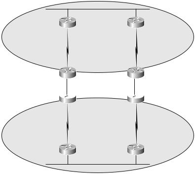
OSPF does a good job of preventing routing loops by preferring certain types of routes to others. However, with an OSPF super-backbone, these loop prevention mechanisms don’t work anymore. To illustrate, look at Figure 7.15; two sites are redundantly connected through a service provider’s OSPF super-backbone.
F I G U R E 7 . 1 5 Two sites redundantly connected through an OSPF super-backbone
|
Area 0 |
Site1_R1 |
Site1_R2 |
PE1 |
|
PE2 |
|
Service provider network |
|||
|
Super-backbone |
PE3
 PE4
PE4
Site2_R1 |
Site2_R2 |
Area 1
When routes are received from the two sites by the service provider’s PE routers, their attributes are preserved in the new BGP extended community and carried through the service provider’s OSPF super-backbone. When the routes are redistributed back into OSPF and advertised to each site, they will be LSA Type 3 (O IA). These routes will be propagated through each site and may result in a routing loop when redistributed back into the service provider’s OSPF super-backbone. Figure 7.16 illustrates this situation.
Copyright ©2002 SYBEX, Inc., Alameda, CA |
www.sybex.com |

274 Chapter 7 MPLS VPNs and OSPF
F I G U R E 7 . 1 6 A possible routing loop
Area 0
Site1_R1 |
Site1_R2 |
Redistribution |
|
Redistribution |
|
PE1 |
PE2 |
Service provider network |
Super-backbone |
PE3 |
PE4 |
Redistribution |
|
Redistribution |
|
Site2_R1 |
Site2_R2 |
Area 1
The OSPF super-backbone is the MP-IBGP backbone.
Down Bit
A new mechanism called the down bit is used to prevent routing loops between customer routes and the service provider OSPF super-backbone. When a route is redistributed from MP-IBGP into OSPF, the down bit is set in the Options field of the OSPF LSA header. Another PE router, receiving an LSA with the down bit set, does not redistribute the route into MP-IBGP. Simply put, routes redistributed from MP-IBGP get set with a down bit. Another PE router does not redistribute the same route back into MP-IBGP.
In Figure 7.17, each PE router sets the down bit when a route is redistributed from the OSPF super-backbone (MP-IBGP) into OSPF. When
Copyright ©2002 SYBEX, Inc., Alameda, CA |
www.sybex.com |

MP-BGP and OSPF 275
another PE router connected to the same OSPF area receives the route, it is not redistributed.
F I G U R E 7 . 1 7 A down bit network example
Area 0
Site1_R1
PE1 
D
|
|
|
|
|
|
|
|
|
t |
|
|
|
|
|
|
|
|
|
e |
|
|
|
|
|
|
|
|
|
s |
|
||
|
|
|
|
|
t |
|
|
|
||
|
|
|
|
i |
|
|
|
|
||
|
w |
n |
b |
|
|
|
|
|
|
|
|
|
|
|
|
|
|
|
t |
||
|
|
|
|
|
|
|
|
|
||
o |
|
|
|
|
|
|
|
|
|
e |
|
|
|
|
|
|
|
|
u |
||
|
|
|
|
|
|
|
|
|
ib |
|
|
|
|
|
|
|
|
|
|
r |
|
|
|
|
|
|
|
|
|
t |
|
|
|
|
|
|
|
|
|
s |
|
|
|
|
|
|
|
e |
d |
i |
|
|
|
|
|
|
|
r |
|
|
|
|
|
||
|
|
t |
|
|
|
|
|
|
||
|
|
|
|
|
|
|
|
|
||
|
|
|
|
|
|
|
|
|
|
|
|
|
’ |
|
|
|
|
|
|
|
|
|
n |
|
|
|
|
|
|
|
|
|
|
o |
|
|
|
|
|
|
|
|
|
D |
|
|
|
|
|
|
|
|
|
|
D |
|
Site1_R2 |
o |
|
|
n |
|
|
’ |
|
|
t |
|
|
r |
||
e |
||
|
d |
|
|
|
i |
|
|
s |
|
|
t |
|
|
r |
D |
|
i |
|
b |
|
o |
|
|
|
u |
|
w |
|
t |
n |
e |
|
|
||
b |
||
|
i |
|
|
t |
|
|
|
s |
|
|
e |
|
|
t |
 PE2
PE2
Service provider network
PE3
Site2_R1
D |
|
o |
|
w |
|
n |
|
b |
|
i |
|
t |
|
D |
s |
o |
e |
t |
|
n |
|
’ |
|
t |
|
r |
|
e |
|
d |
|
|
i |
|
s |
|
t |
|
r |
|
i |
|
b |
|
u |
|
t |
|
e |
|
|
|
|
|
|
|
e |
||
|
|
|
|
|
|
|
t |
|
|
|
|
|
|
|
|
|
u |
|
|
|
|
|
|
|
|
b |
|
|
|
|
|
|
|
|
|
i |
|
|
|
|
|
|
|
|
|
r |
|
|
|
|
|
|
d |
i |
s |
t |
|
|
|
|
|
e |
|
|
|
|
|||
|
|
|
|
|
|
|
|
||
|
|
|
|
|
|
|
|
|
|
|
r |
|
|
|
|
|
|
t |
|
|
’t |
|
|
|
|
|
|
|
|
D |
n |
|
|
|
|
|
|
s |
e |
o |
|
|
|
|
|
t |
|
|
|
|
|
|
|
|
|
b |
i |
|
|
|
|
|
n |
|
|
|
|||
|
|
w |
|
|
|
|
|
|
|
|
o |
|
|
|
|
|
|
|
|
|
D |
|
|
|
|
|
|
|
|
Super-backbone
PE4
Site2_R2
Area 1
OSPF Tag Field
The down bit does not prevent every possible routing loop. When a route crosses from one OSPF domain to another, it may lose its down bit setting. By default, routes redistributed from BGP into OSPF (standard LSA Type 5 external routes) map the BGP AS number to the tag field of the external route. Another PE, seeing its own AS number in the tag field, does not redistribute the route into MP-IBGP, as illustrated in Figure 7.18.
It’s important to note that you only get the tag field for external OSPF routes (Type 5) and not intra-area (O) and inter-area (O IA) routes. To get around this, you could simply configure the PE to only redistribute into
Copyright ©2002 SYBEX, Inc., Alameda, CA |
www.sybex.com |

276 Chapter 7 MPLS VPNs and OSPF
MP-IBGP internal OSPF routes. An alternate method of setting the tag field is to have the router between the two OSPF domains set the tag field manually using the redistribute ospf process-id tag # command.
F I G U R E 7 . 1 8 A tag field network example
Super-backbone
MP-IBGP
AS# 65000
Tag = 65000 |
Tag = 65000 |
OSPF Domain 1 |
OSPF Domain 2 |
Path Selection
Given the complexities of customer connections to a service provider network, path selection becomes a concern. More than likely, you don’t want a customer network being used as a transit for VPN traffic. To ensure proper path selection, Cisco IOS routers use an internal IOS mechanism called the routing bit. When a PE router receives a route with the down bit set, the routing bit is cleared. With the routing bit cleared, a route never shows up in the routing table of the PE, even if it is the best route as determined by OSPF.
Again, the routing bit is an internal IOS mechanism on the router and is not sent to any neighboring OSPF routers in the customer network.
CE-to-PE Protocol Selection
Just because OSPF is discussed in this chapter does not mean that OSPF is the recommended routing protocol for use between CE and PE routers. OSPF has a lot of overhead associated with it due to its operation. As more and more OSPF routing processes are configured on a router, the router has more overhead, and its operation may be slowed.
Copyright ©2002 SYBEX, Inc., Alameda, CA |
www.sybex.com |