

VPNs 101 129
Categories of VPNs
In addition to topological definitions, VPNs can also be categorized by the business need they fill or by the characterization of services they provide. There are three categories of VPNs:
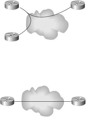
Intranets An intranet is a collection of sites that are controlled by the same organization. An example of an intranet is a single company with all its sites connected together in a single network. Figure 4.13 shows multiple sites connected in an intranet.
F I G U R E 4 . 1 3 A simple intranet
Miami headquarters |
VC1 |
Orlando office |
|
|
|
|
VC2 |
|
Tampa office
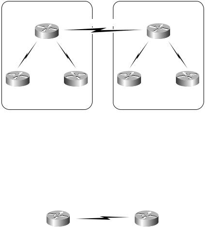
Extranet An extranet is a connection between two or more organizations. An example of an extranet might be a company with a connection to a partner company. Figure 4.14 shows two company sites connected together in an extranet.
F I G U R E 4 . 1 4 A simple extranet
Virtual circuits (VCs)
Company A Company B
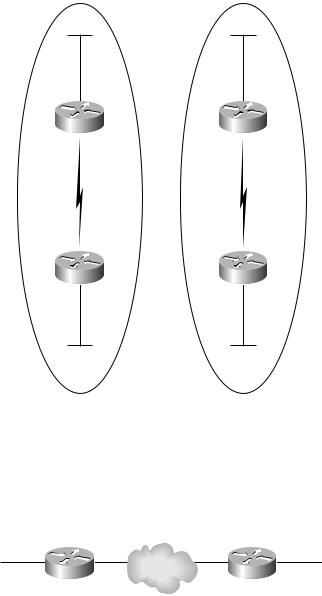
Combination of intranets and extranets Oftentimes, VPNs are a combination of both intranets and extranets. Figure 4.15 shows two companies with both intranets and extranets deployed.
Copyright ©2002 SYBEX, Inc., Alameda, CA |
www.sybex.com |
130 Chapter 4 VPNs: An Overview
In Figure 4.15, both Company A and Company B have an intranet deployed. A separate connection runs between the headquarters of Company A and Company B, creating the extranet. An extranet poses a security risk not present in intranets because Company A may have unauthorized access to Company B’s network (and vice versa). In the combination network, both Company A and Company B must take efforts to secure their sites.
F I G U R E 4 . 1 5 A two-company network with intranets and extranets
Company A intranet |
Company B intranet |
Company A |
Company B |
Headquarters |
Headquarters |
Miami |
Atlanta |
|
Extranet connection |
Company A |
Company A |
Company B |
Company B |
Site office |
Site office |
Site office |
Site office |
Orlando |
Tampa |
Augusta |
Macon |
VPN Routing
So now that you know about the various VPN topologies, you need to know about routing inside a VPN. Figure 4.16 illustrates a simple network, with two customer sites connected with point-to-point links.
F I G U R E 4 . 1 6 A simple point-to-point network
|
|
.1/16 |
.1/16 |
|
.2/16 |
.1/16 |
|
||
|
|
.0 |
.0 |
|
.0 |
.0 |
|
||
|
|
.1 |
.2 |
|
.2 |
.3 |
|
||
|
|
10 |
10 |
|
10 |
10 |
|
||
|
|
|
|
|
|
|
|
|
|
|
|
|
|
|
|
|
|
|
|
10.1.0.0 |
|
R1 |
|
10.2.0.0 |
R2 |
10.3.0.0 |
|||
Copyright ©2002 SYBEX, Inc., Alameda, CA |
www.sybex.com |

VPNs 101 131
Table 4.1 lists the IP addresses and interfaces of the network devices in Figure 4.16.
T A B L E 4 . 1 Point-to-Point Network Addressing
Device |
Interface |
IP Address |
|
|
|
R1 |
Serial 0 |
10.2.0.1 |
R1 |
Ethernet0 |
10.1.0.1 |
R2 |
Serial 0 |
10.2.0.2 |
R2 |
Ethernet0 |
10.3.0.1 |
|
|
|
Instead of just adding the routing table to this section, let’s go through a routing table exercise that I use in my classes. We’ll start with R1. What are the connected interfaces? 10.2.0.1 and 10.1.0.1. Suppose the router has a 16-bit mask (/16 or 255.255.0.0). What are the two networks that R1 knows about as being directly connected? 10.2.0.0 and 10.1.0.0.
Now let’s move to R2. What are the connected interfaces on R2? 10.2.0.2 and 10.3.0.1. Using a 16-bit mask, the two networks that R2 knows are directly connected are 10.2.0.0 and 10.3.0.0. So based on the information you have so far, you can build two routing tables. Table 4.2 contains the routing table for R1, and Table 4.3 contains the routing table for R2.
T A B L E 4 . 2 R1 Routing Table
Network |
Method |
Interface |
|
|
|
10.1.0.0 |
Directly connected |
Ethernet0 |
10.2.0.0 |
Directly connected Serial 0 |
Serial 0 |
|
|
|
T A B L E 4 . 3 R2 Routing Table
Network |
Method |
Interface |
|
|
|
10.3.0.0 |
Directly connected |
Ethernet0 |
10.2.0.0 |
Directly connected Serial 0 |
Serial 0 |
|
|
|
Copyright ©2002 SYBEX, Inc., Alameda, CA |
www.sybex.com |
132 Chapter 4 VPNs: An Overview
What happens to the routing tables when a routing protocol is enabled such as RIP? The router R1 advertises 10.1.0.0 to R2. The router R2 advertises 10.3.0.0. Table 4.4 contains the new routing table for R1, and Table 4.5 contains the new routing table for R2.
T A B L E |
4 . 4 |
R1 Routing Table with RIP |
|
|
|
|
|
|
|
|
|
|
|
Network |
Method |
Interface |
|
|
|
|
|
|
|
|
|
10.1.0.0 |
Directly connected |
Ethernet0 |
|
|
|
10.2.0.0 |
Directly connected |
Serial 0 |
|
|
|
10.3.0.0 |
RIP |
Serial 0 |
|
T A B L E |
4 . 5 |
|
|
|
|
R2 Routing Table with RIP |
|
|
|||
|
|
|
|
|
|
|
|
Network |
Method |
Interface |
|
|
|
|
|
|
|
|
|
10.1.0.0 |
RIP |
Serial 0 |
|
|
|
10.2.0.0 |
Directly connected |
Serial 0 |
|
|
|
10.3.0.0 |
Directly connected |
Ethernet0 |
|
|
|
|
|
|
|
There’s a reason that I’m going through all this basic material for you. First of all, there is no service provider infrastructure showing up on the customer routers R1 and R2. R1 and R2 are totally oblivious to anything behind their point-to-point connection. In addition, the service provider is totally oblivious to the IP addressing and routing protocols being run on the customer routers. R1 and R2 are on a private and isolated connection. If the customers misconfigure an IP address or a routing protocol, the service provider is unaware of it.
Since point-to-point networks are well isolated and private, it is possible to have customers using the exact same IP addressing scheme. For example, suppose a consultant sets up a network for Customer A using an IP addressing scheme of 10.1.0.0, 10.2.0.0, and 10.3.0.0. And suppose the very same consultant sets up a network for Customer B using 10.1.0.0, 10.2.0.0, and 10.3.0.0. Figure 4.17 illustrates the point-to-point networks for both Customer A and Customer B.
Copyright ©2002 SYBEX, Inc., Alameda, CA |
www.sybex.com |
VPNs 101 133
F I G U R E 4 . 1 7 Point-to-point networks for Customer A and Customer B
Customer A |
Customer B |
10.3.0.0 |
10.3.0.0 |
10.2.0.0 |
10.2.0.0 |
10.1.0.0 |
10.1.0.0 |
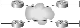
VPNs came about as a less expensive alternative to point-to-point links. Figure 4.18 illustrates a simple VPN with two customer sites connected with a single VC, simulating the original point-to-point connectivity illustrated in Figure 4.17.
F I G U R E 4 . 1 8 A simple VPN with two customer sites
10.1.0.0 |
10.2.0.0 |
10.3.0.0 |
||
|
||||
|
|
Virtual circuits |
|
|
|
|
|
|
|
|
|
(VCs) |
|
|
|
R1 |
R2 |
||
|
|
|||
Table 4.6 lists the IP addresses and interfaces of the network devices in Figure 4.18.
Copyright ©2002 SYBEX, Inc., Alameda, CA |
www.sybex.com |

134 Chapter 4 VPNs: An Overview
T A B L E 4 . 6 VPN Addressing
Device |
Interface |
IP Address |
|
|
|
R1 |
Serial 0 |
10.2.0.1 |
R1 |
Ethernet0 |
10.1.0.1 |
R2 |
Serial 0 |
10.2.0.2 |
R2 |
Ethernet0 |
10.3.0.1 |
|
|
|
Just like the point-to-point example, R1 and R2 build routing tables based on directly connected interfaces. Table 4.7 contains the routing table for R1, and Table 4.8 contains the routing table for R2.
T A B L E 4 . 7 R1 Routing Table
Network |
Method |
Interface |
|
|
|
10.1.0.0 |
Directly connected |
Ethernet0 |
10.2.0.0 |
Directly connected S0 |
Serial 0 |
|
|
|
T A B L E 4 . 8 R2 Routing Table
Network |
Method |
Interface |
|
|
|
10.3.0.0 |
Directly connected |
Ethernet0 |
10.2.0.0 |
Directly connected S0 |
Serial 0 |
|
|
|
When a routing protocol such as RIP is enabled, the router R1 advertises 10.1.0.0 to R2 and the router R2 advertises 10.3.0.0. Table 4.9 contains the new routing table for R1, and Table 4.10 contains the new routing table for R2. Just like point-to-point links, network devices connected together with VCs
in a VPN have no knowledge of the service provider infrastructure. With a VPN, R1 and R2 are totally oblivious to anything behind their VC connection. In addition, the service provider is totally oblivious to the IP addressing and
Copyright ©2002 SYBEX, Inc., Alameda, CA |
www.sybex.com |
VPNs 101 135
routing protocols being run on the customer routers. If the customers misconfigure an IP address or a routing protocol, the service provider is unaware of it.
T A B L E |
4 . 9 |
R1 Routing Table with RIP |
|
|
|
|
|
|
|
|
|
|
|
Network |
Method |
Interface |
|
|
|
|
|
|
|
|
|
10.1.0.0 |
Directly connected |
Ethernet0 |
|
|
|
10.2.0.0 |
Directly connected |
Serial 0 |
|
|
|
10.3.0.0 |
RIP |
Serial 0 |
|
T A B L E |
4 . 1 0 |
|
|
|
|
R2 Routing Table with RIP |
|
|
|||
|
|
|
|
|
|
|
|
Network |
Method |
Interface |
|
|
|
|
|
|
|
|
|
10.1.0.0 |
RIP |
Serial 0 |
|
|
|
10.2.0.0 |
Directly connected |
Serial 0 |
|
|
|
10.3.0.0 |
Directly connected |
Ethernet0 |
|
|
|
|
|
|
|
VPNs result in well-isolated networks with the same privacy as point-to- point connections. With VPNs, it’s possible to have customers using the exact same IP addressing scheme. For example, suppose a consultant sets up a network for Customer A using an IP addressing scheme of 10.1.0.0, 10.2.0.0, and 10.3.0.0. And suppose the very same consultant sets up a network for Customer B using 10.1.0.0, 10.2.0.0, and 10.3.0.0. Figure 4.19 illustrates the VPNs for both Customer A and Customer B.
F I G U R E 4 . 1 9 VPNs for Customer A and Customer B
Customer A |
10.2.0.0 |
Customer A |
|
|
|
10.1.0.0 |
|
10.3.0.0 |
R1 |
Virtual circuit (VC) |
R2 |
|
||
Customer B |
Virtual circuit (VC) |
Customer B |
10.1.0.0 |
|
10.3.0.0 |
R1 |
10.2.0.0 |
R2 |
|
Copyright ©2002 SYBEX, Inc., Alameda, CA |
www.sybex.com |