


104 Chapter 3 MPLS and ATM
T A B L E 3 . 1 Cell-Mode Service Provider Network Device Roles
Device |
Function |
|
|
Site 1 |
Non-MPLS router |
Site 2 |
Non-MPLS router |
Melbourne POP |
Router functioning as an ATM edge-LSR |
Ft. Lauderdale POP |
Router functioning as an ATM edge-LSR |
Orlando_ATM |
ATM switch functioning as an ATM-LSR |
Miami_ATM |
ATM switch functioning as an ATM-LSR |
|
|
The easiest way to discuss label switching in cell-mode MPLS is to first relate it to frame-mode MPLS. If the network in Figure 3.7 is enabled for frame-mode MPLS, what happens? An unlabeled IP packet enters the network, and the ingress edge-LSR applies a label that is used to label-switch the packet through the service provider network, ultimately delivering it to the egress edge-LSR.
How are things different in cell-mode MPLS? An unlabeled packet enters the network, and the ingress ATM edge-LSR uses the VPI/VCI mappings as the label. Each ATM-LSR in the LSP through the service provider network switches the packet based solely on the VPI/VCI values. That’s it! Just remember: in cell-mode MPLS, labels equal VPI/VCI values.
VC Merge
Cisco ATM-LSRs make use of a function called virtual circuit merge (VC merge) to solve the cell-interleaving problem and reduce the number of labels used in the ATM-LSR network, or ATM-LSR domain.
An ATM-LSR domain is a series of ATM-LSRs connected together with
LC-ATM interfaces.
Let’s start with the problem called cell interleaving.
Copyright ©2002 SYBEX, Inc., Alameda, CA |
www.sybex.com |
Cell-Mode MPLS 105
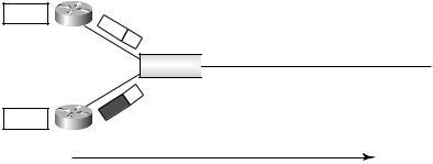
In Figure 3.8, an IP packet enters the network at the POP 1 router. The POP 1 router performs a lookup, and the mapping of label to the VPI/VCI value is identified. The IP packet is broken up, or segmented, into ATM cells, and the VPI/VCI value is applied to each cell as it is sent to ATM 1. For simplicity’s sake, the cells from POP 1 are illustrated in Figure 3.8 with a label; in reality, it’s a VPI/VCI value.
F I G U R E 3 . 8 Cell interleaving
IP
POP 1
IP
POP 2
9
15
ATM |
|
|
|
|
|
|
|
|
|
|
? |
|
|
|
42 |
|
42 |
|
42 |
|
|
42 |
|
ATM 1 |
|
|
|
|
|
|
|||||
|
|
|
|
|
|
|
|
|
|
||
Traffic flow |
|
|
|
|
|
|
|
|
|||
Also in Figure 3.8, an IP packet enters the network at the POP 2 router. The POP 2 router performs a lookup, and the mapping of a label to the VPI/ VCI value is identified. The IP packet is broken up, or segmented, into ATM cells, and the VPI/VCI value is applied to each cell as it is sent to ATM 1.
Again, for simplicity’s sake, the cells from POP 2 are illustrated with a label; in reality, it’s a VPI/VCI value.
To view the number of tags used, execute the show tag-switching atmtdp summary command. The local value in the field tells you how many tags have been assigned by the TSR on the interface. The corresponding MPLS command can be found at www.cisco.com.
R1#show tag-switching atm-tdp summary
Total number of destinations: 691
TC-ATM bindings summary |
|
|
|
|
||
interface |
total |
active |
bindwait |
local |
remote |
other |
ATM0/0/0 |
490 |
488 |
1 |
300 |
302 |
1 |
If the ATM switch (in Figure 3.8, it’s called ATM 1) uses the same label for cells traveling to a common destination, the receiving device does not know how to reassemble the cells into packets. How can this problem be fixed? By using multiple labels for each flow. Look at Figure 3.9. On ATM 1,
Copyright ©2002 SYBEX, Inc., Alameda, CA |
www.sybex.com |
106 Chapter 3 MPLS and ATM
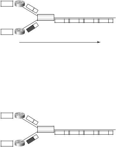
the flow of cells from POP 1 uses label 49, and the flow of cells from POP 2 uses label 61. When these cells are received by an end device that needs to reassemble the cells back into packets, it’s easy to tell the cells apart by their labels.
F I G U R E 3 . 9 Cells with multiple labels
IP |
|
POP 1 |
9 |
|
15 |
IP |
|
POP 2 |
|
ATM
 49
49  61
61  49
49  61
61
ATM 1
Traffic flow
There is one drawback to this solution. ATM 1 uses many labels. For each flow, ATM 1 sends a downstream-on-demand–style request to its downstream ATM-LSR, requesting labels for each flow.
VC merge fixes cell interleaving and reduces the number of labels required by buffering cell flows and forwarding them in a serialized fashion. Consider the example illustrated in Figure 3.10. The cell flow from POP 2 is buffered, while the flow of cells from POP 1 is sent out the outbound interface. When the cell flow from POP 1 is complete, the cell flow from POP 2 is sent out the outbound interface. A downstream device needing to reassemble the cells receives each flow in order.
F I G U R E 3 . 1 0 An ATM network with VC merge
IP
POP 1
IP
POP 2
9
15
ATM
 42
42  42
42  42
42  42
42
ATM 1
Through VC merge, an ATM-LSR can reuse the same label for multiple cell flows. VC merge solves the cell-interleaving problem and allows the ATM-LSR to preserve label space. VC merge is enabled on ATM-LSRs by
Copyright ©2002 SYBEX, Inc., Alameda, CA |
www.sybex.com |