

Running RIP in an MPLS VPN 213
PE1(config-router)#address-family ipv4 vrf vpn_b
PE1(config-router-af)#network 10.0.0.0
Now RIPv2 is running, in separate contexts, for both Customer A and Customer B. To verify that everything works right, run the show ip router vrf vpn_name command and look for routes being learned from the customer routers.
Configuring Redistribution
As mentioned earlier in this chapter, to get routes from one side of the network to the other, you need to do redistribution. RIP is running in the VRF.
How do you get routes from context RIP into MP-BGP? With the redistribute command.
Redistribution is a little different with MP-BGP than with regular BGP. When you make a VRF, an MP-BGP routing context is created and accessed under the address-family ipv4 vrf vpn_name section in MP-BGP. So MP-BGP has a routing context for a particular VRF, just like RIP.
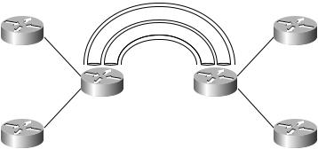
A good way to think about it is that there is a conduit for each VPN running inside MP-BGP. Figure 6.7 illustrates this principle.
F I G U R E 6 . 7 MP-BGP conduits
MP-IBGP
VP
N_a
VP |
N |
_b |
|
Customer A1 |
Customer A2 |
PE1 |
PE2 |
Customer B1 |
Customer B2 |
Redistribution is a two-way process—from RIP into BGP and from BGP into RIP. On PE1, for Customer A, the following configuration is required for redistribution:
PE1#config t
PE1(config)#router rip
Copyright ©2002 SYBEX, Inc., Alameda, CA |
www.sybex.com |

214 Chapter 6 MPLS VPNs and RIP
PE1(config-router)#address-family ipv4 vrf vpn_a
PE1(config-router-af)#redistribute bpg 1 metric transparent
PE1(config-router-af)#exit
PE1(config-router)#exit
PE1(config)#router bgp 1
PE1(config-router)#address-family ipv4 vrf vpn_a
PE1(config-router-af)#redistribute rip
If you are experienced with BGP, you may be interested in the metric transparent. With the metric transparent in the redistribute command, the service provider MP-IBGP backbone preserves the RIP hop count. The RIP hop count is carried in the MED. From RIP, the hop count goes in the MED. Redistribution from MP-IBGP back into RIP copies the MED (hop count) back into the RIP hop count.
For Customer B, the configuration for redistribution needs to be repeated as follows:
PE1#config t
PE1(config)#router rip
PE1(config-router)#address-family ipv4 vrf vpn_b
PE1(config-router-af)#redistribute bpg 1 metric transparent
PE1(config-router-af)#exit
PE1(config-router)#exit
PE1(config)#router bgp 1
PE1(config-router)#address-family ipv4 vrf vpn_b
PE1(config-router-af)#redistribute rip
Route Targets
Thought you were done? Wrong! There’s one last item to configure: route targets. Route targets are carried in extended BGP communities. They are 64 bits in length (only 48 bits of which can be configured), and they’re used to support complex VPN topologies. A route target is the closest thing to a VPN identifier that exists. A route target is similar to a route distinguisher. The two ways to configure a route target are 16-bit:32-bit or 32-bit:16-bit.
Copyright ©2002 SYBEX, Inc., Alameda, CA |
www.sybex.com |
Running RIP in an MPLS VPN 215
There are two types of route targets:
Export Route Target When routes are redistributed from a routing protocol context (that’s the address-family ipv4 part), they get tagged with an export route target when they are redistributed into MP-BGP. The route target is carried with the route from one PE device to another.
Import Route Target When routes are redistributed from MP-BGP into a routing protocol context for a VRF, the PE uses the configured import route target value to match routes for redistribution.
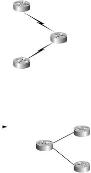
Let’s go through an example to see how route targets work. In Figure 6.8, vpn_a and vpn_b routes on PE1 are redistributed into MP-BGP.
F I G U R E 6 . 8 Routes from PE1 into MP-BGP
|
|
|
|
ip vrf vpn_a |
||
|
|
Customer A1 |
rd 1:1 |
|||
|
|
|
|
|
||
10.1.0.0/16 |
|
R |
10.1.0.0 |
|
||
|
|
|
|
|||
|
|
|
||||
|
|
|
C |
10.2.0.0 |
|
|
|
10.2.0.0 |
|||||
|
|
|
|
|
||
|
|
|
|
|||
|
|
|
|
|
|
|
|
|
|
|
ip vrf vpn_b |
||
|
|
|
PE1 |
rd 1:2 |
||
|
|
10.2.0.0 |
R |
10.1.0.0 |
|
|
10.1.0.0/16 |
|
C |
10.2.0.0 |
|
||
|
|
|
|
|||
|
Customer B1 |
|
|
|
||
|
|
|
|
|||
|
|
|
|
|
||
|
|
|
|
|
||
|
|
|
|
|
|
|
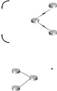
Figure 6.9 illustrates routes from PE1 as they arrive at PE2.
F I G U R E 6 . 9 Routes from PE1 arriving at PE2
From PE1 |
Customer A2 |
|||
|
|
|
|
|
|
MP-IBGP |
|
||
|
RD |
|
NLRI |
|
|
1:1 |
10.1.0.0 |
PE2 |
|
|
1:1 |
10.2.0.0 |
||
|
|
|||
|
1:2 |
10.1.0.0 |
|
|
|
1:2 |
10.2.0.0 |
Customer B2 |
|
Copyright ©2002 SYBEX, Inc., Alameda, CA |
www.sybex.com |
216 Chapter 6 MPLS VPNs and RIP
How does PE2 know which routes need to be redistributed into its VPNs? The route distinguisher could be used, but it’s too simple to support more complex topologies because there is only one route distinguisher value specified.
Figure 6.10 shows routes from PE2 as they are redistributed into MP-BGP.
F I G U R E 6 . 1 0 Routes from PE2 into MP-BGP
ip vrf vpn_a rd 1:1
|
|
|
R |
10.4.0.0 |
|
Customer A2 |
|||
|
|
|
C |
10.3.0.0 |
|
||||
|
|
|
|
|
|
|
|
||
MP-IBGP |
|
|
|
10.3.0.0/16 |
|
|
10.4.0.0/16 |
||
|
|
|
|
|
|||||
|
|
|
|
|
|
||||
|
|
|
|
|
|
||||
|
|
|
|
|
|
||||
|
|
|
|
|
|
|
|||
|
|
|
|
|
|
|
|
|
|
RD |
NLRI |
|
|
|
|
|
|
|
|
1:1 |
10.3.0.0 |
|
|
|
|
|
|
|
|
1:1 |
10.4.0.0 |
|
|
|
|
PE2 |
|||
1:2 |
10.3.0.0 |
|
ip vrf vpn_b |
||||||
|
10.3.0.0/16 |
|
|
|
|||||
1:2 |
10.4.0.0 |
|
rd 1:2 |
|
|
|
10.4.0.0/16 |
||
|
|
||||||||
|
|
|
R |
10.4.0.0 |
|
Customer B2 |
|
||
|
|
|
|
|
|
||||
|
|
|
C |
10.3.0.0 |
|
|
|
||
|
|
|
|
|
|
|
|
|
|
Figure 6.11 illustrates routes from PE2 as they are received at PE1.
F I G U R E 6 . 1 1 Routes from PE2 arriving at PE1
Customer A1 |
|
|
|
From PE2 |
|
|
|
|
|
||
|
|
MP-IBGP |
|||
|
|
RD |
NLRI |
|
|
|
PE1 |
1:1 |
10.3.0.0 |
|
|
|
1:1 |
10.4.0.0 |
|
||
|
|
|
|||
|
|
1:2 |
10.3.0.0 |
|
|
Customer B1 |
|
1:2 |
10.4.0.0 |
|
|
How does PE1 know which routes need to be redistributed into its VPNs? Again, the route distinguisher could be used, but it is not an effective solution for complex topologies. The route target feature was developed because route distinguishers don’t work for complex topologies.
Copyright ©2002 SYBEX, Inc., Alameda, CA |
www.sybex.com |