
- •Acknowledgments
- •Introduction
- •Assessment Test
- •Answers to Assessment Test
- •Service Provider Networks
- •Scalability
- •Traffic Engineering
- •Quality of Service
- •MPLS Label Stack
- •Shim Header
- •MPLS Architecture
- •Control
- •Forwarding
- •MPLS Label Switching
- •MPLS Network Components
- •Device Output
- •Label-Switched Paths
- •MPLS Applications
- •MPLS and ATM
- •Overlay
- •Quality of Service
- •Traffic Engineering
- •Summary
- •Exam Essentials
- •Key Terms
- •Review Questions
- •Answers to Review Questions
- •Routing Review
- •Frame-Mode MPLS Working Example
- •Network Routing Protocol Examples
- •MPLS Step by Step
- •Label Distribution
- •Assigning Labels
- •Troubleshooting and Verification
- •Device Configuration
- •IGP Verification
- •CEF Verification
- •MPLS Verification
- •Label Distribution and Bindings
- •Binding Verification
- •Troubleshooting the Network
- •Hiding Service Provider Devices
- •Summary
- •Exam Essentials
- •Key Terms
- •Review Questions
- •Answers to Review Questions
- •Frame-Mode MPLS and ATM
- •Frame-Mode MPLS and ATM Configuration
- •Cell-Mode MPLS
- •Label Binding with ATM
- •Cell-Mode Label Switching
- •VC Merge
- •Loop Prevention
- •Cell-Mode MPLS Configuration
- •Summary
- •Exam Essentials
- •Key Terms
- •Review Questions
- •Answers to Review Questions
- •VPNs 101
- •Point-to-Point Connections
- •Virtual Private Networks
- •Categories of VPNs
- •VPN Routing
- •Peer-to-Peer VPNs
- •Optimal Routing
- •Peer-to-Peer Security
- •Peer-to-Peer VPN Routing
- •Summary
- •Exam Essentials
- •Key Terms
- •Review Questions
- •Answers to Review Questions
- •Service Provider Configuration
- •MPLS VPNs
- •Virtual Router
- •Virtual Routing and Forwarding Tables
- •MPLS Operational Overview
- •MP-BGP Configuration
- •An MPLS VPN Example
- •Route Distinguisher
- •MP-IBGP Configuration Example
- •Initial Network Configuration
- •MP-IBGP Configuration
- •Verification
- •Summary
- •Exam Essentials
- •Key Terms
- •Review Questions
- •Answers to Review Questions
- •A Review of VPNs
- •Configuring a Simple MPLS VPN
- •Configuring VRF Interfaces
- •Running RIP in an MPLS VPN
- •Configuring RIPv2 with Address-Family ipv4
- •Configuring Redistribution
- •Route Targets
- •Configuring Route Targets
- •A Review of Simple VPN Configuration
- •Configuring MPLS in the Service Provider Network
- •Simple VPN Configuration
- •Configuring the PE-CE Routing Protocol
- •Lab: Configuring an MPLS VPN
- •Configuring POP Routers
- •VPN Configuration
- •Raleigh Running-Config
- •Atlanta Running-Config
- •Peer 1 Running-Config
- •Peer 2 Running-Config
- •Verification with Ping
- •Routing Table Isolation
- •Verifying VRF Routes
- •Summary
- •Exam Essentials
- •Key Terms
- •Review Questions
- •Answers to Review Questions
- •MP-BGP and OSPF
- •A Review of OSPF
- •OSPF Router Types
- •Link State Advertisements
- •OSPF for MPLS VPNs
- •OSPF Super-Backbone
- •Preventing Routing Loops
- •Path Selection
- •MPLS VPN OSPF Lab
- •Summary
- •Exam Essentials
- •Key Terms
- •Review Questions
- •Answers to Review Questions
- •Static Routing
- •Device Configuration
- •VPN Configuration
- •Raleigh Running-Config
- •Atlanta Running-Config
- •Peer Router Configuration
- •Verification with Ping
- •Verifying Static VRF Routes
- •E-BGP and MPLS VPNs
- •Device Configuration
- •E-BGP Operation
- •AS-Override
- •VPN Configuration
- •Raleigh Running-Config
- •Atlanta Running-Config
- •Peer Router Configuration
- •Peer 1 Running-Config
- •Peer 2 Running-Config
- •Verification with Ping
- •Advanced MPLS VPN Topologies
- •Simple VPNs
- •Central Services MPLS VPN Topology
- •Overlay MPLS VPN Topology
- •Summary
- •Exam Essentials
- •Key Terms
- •Review Questions
- •Answers to Review Questions
- •Challenge Lab 1
- •MPLS
- •MP-IBGP
- •Answer to Lab 1.1
- •Answer to Lab 1.2
- •Answer to Lab 1.3
- •Challenge Lab 2
- •Tag Switching
- •MP-IBGP
- •Answer to Lab 2.1
- •Answer to Lab 2.2
- •Answer to Lab 2.3
- •Challenge Lab 3
- •VRF Configuration
- •RIPv2
- •Redistribution
- •Answer to Lab 3.1
- •Answer to Lab 3.2
- •Answer to Lab 3.3
- •Challenge Lab 4
- •VRF Configuration
- •OSPF
- •Redistribution
- •Answer to Lab 4.1
- •Answer to Lab 4.2
- •Answer to Lab 4.3
- •Challenge Lab 5
- •VRF Configuration
- •Static Routes and Redistribution
- •Answer to Lab 5.1
- •Answer to Lab 5.2
- •Challenge Lab 6
- •VRF Configuration
- •E-BGP Configuration
- •Answer to Lab 6.1
- •Answer to Lab 6.2
- •Service Provider Network Configuration with OSPF
- •Router Configuration
- •Routing Tables
- •Tags
- •Service Provider Network Configuration with IS-IS
- •Router Configuration
- •Routing Tables
- •Tag Switching Forwarding Tables
- •Glossary
136 Chapter 4 VPNs: An Overview
Peer-to-Peer VPNs
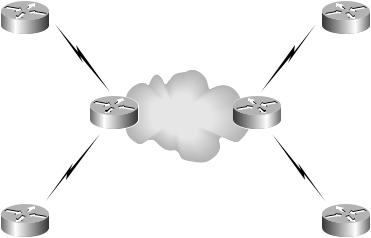
Service providers, in an effort to offer improved services to customers, began to implement peer-to-peer VPNs a few years ago. Peer-to-peer VPNs are a departure from the traditional overlay VPNs. The biggest difference between peer-to-peer VPNs and traditional VPNs is that a customer router peers with a service provider device instead of with another customer device.
Figure 4.20 illustrates a peer-to-peer VPN.
F I G U R E 4 . 2 0 A peer-to-peer VPN network
Customer A1 |
Customer A2 |
|
Service provider |
|
network |
PE1 |
PE4 |
Customer B1 |
Customer B2 |
For the more experienced reader, Figure 4.20 is extremely scary. In Figure 4.20, customer routers actually peer with service provider devices. If you remember back to how traditional VPNs operated, the service provider network was transparent to the customer. With a traditional overlay VPN, the customer and service provider networks were well isolated from one another. Now, as you can see in Figure 4.20, the service provider network is visible.
Let’s discuss peer-to-peer VPNs in more detail.
Optimal Routing
There are many benefits associated with peer-to-peer VPNs. The first of these benefits is optimal routing. To get optimal routing with a traditional
Copyright ©2002 SYBEX, Inc., Alameda, CA |
www.sybex.com |
Peer-to-Peer VPNs 137
VPN, you need a full-mesh topology. You may recall that a full-mesh topology is expensive (in addition to being complex). To illustrate how peer-to-peer VPNs offer optimal routing, let’s look at an example.
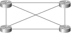
First, let’s talk about optimal routing with an overlay VPN. In Figure 4.21, four customer sites in New York, Raleigh, Atlanta, and D.C. are connected with VCs in a full-mesh topology.
F I G U R E 4 . 2 1 A full-mesh VPN with four customer sites
New York |
Raleigh |
|
VC4 |
|
VC6 |
VC1 |
VC3 |
|
VC5 |
|
VC2 |
Atlanta |
D.C. |
Figure 4.21 illustrates optimal routing. Notice that traffic from New York to Atlanta is directed over VC1. Traffic from New York to Raleigh is directed over VC4. Traffic from New York to D.C. is directed over VC6. Optimal routing is achieved through a full-mesh topology.
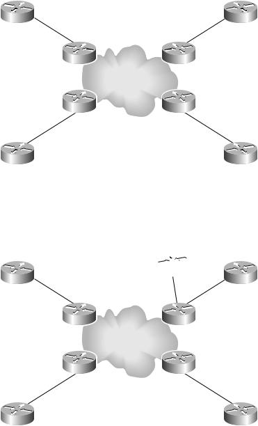
In Figure 4.22, the very same sites are connected with a peer-to-peer VPN. Customer sites use public addresses, and their routes are carried by the service provider. When traffic from New York needs to get to Atlanta, the next hop router is PE1. It is up to the service provider to make sure that traffic takes the most optimal path between New York and Atlanta. Traffic from New York to D.C. goes to PE1, and again it is up to the service provider to make sure that traffic follows the optimal path to D.C.
Notice the number of connections in Figure 4.22. The New York router has a single connection to PE1, Atlanta has a single connection to PE2, Raleigh has a single connection to PE3, and D.C. has a single connection to PE4. To add another site into the peer-to-peer VPN, from a connection standpoint, only requires one new connection between the new customer site and a service provider PE router. This is much better than needing to set up, or provision, a whole new set of VCs to create a full mesh in a traditional VPN.
Copyright ©2002 SYBEX, Inc., Alameda, CA |
www.sybex.com |
138 Chapter 4 VPNs: An Overview
F I G U R E 4 . 2 2 A peer-to-peer VPN with four customer sites
New York |
Raleigh |
PE1 |
PE3 |
PE2 |
PE4 |
Atlanta |
D.C. |
Adding a site to a peer-to-peer VPN is illustrated in Figure 4.23. Notice that the Charlotte site is connected to the service provider router PE3, along with the Raleigh site.
F I G U R E 4 . 2 3 Peer-to-peer VPN provisioning
Charlotte 
New York |
Raleigh |
PE1 |
PE3 |
PE2 |
PE4 |
Atlanta |
D.C. |
Copyright ©2002 SYBEX, Inc., Alameda, CA |
www.sybex.com |

Peer-to-Peer VPNs 139
Peer-to-Peer Security
So far, you’ve learned about peer-to-peer VPNs from the standpoint of optimal routing and ease of provisioning. You may recall that one of the selling features of VPNs is the security and privacy of a dedicated point-to-point connection without the cost. This is a section on peer-to-peer VPNs, so there must be some privacy and security. Well, there is privacy and security, but only after someone configures it.
Let’s look at an example. Figure 4.24 illustrates a simple peer-to-peer VPN that I’ll use to discuss peer-to-peer VPN security.
F I G U R E 4 . 2 4 A simple peer-to-peer VPN
New York |
PE1 |
PE4 |
D.C. |
How do you provide security to the New York and D.C. sites? Access lists? Too risky. If someone on the service provider side misconfigures an access list, you can lose security. How do you provide some type of privacy? Route filters? Too time-consuming. As you can tell, I’m not a fan of all the management required for peer-to-peer VPNs.
Peer-to-Peer VPN Routing
Before learning more detailed information about peer-to-peer VPNs, you need to understand routing inside peer-to-peer VPNs. The important thing to remember about routing in a peer-to-peer VPN is that the service provider network is responsible for optimal site-to-site routing. Since the service provider is responsible for optimal transport, it needs to know all the network routes. In traditional VPNs, the service provider did not know the details of customer routing; in peer-to-peer VPNs, it must.
With peer-to-peer VPNs, a service provider now knows the IP networks used by customers. Peer-to-peer VPNs do not support overlapping addresses or private addresses without per-site address translation.
Copyright ©2002 SYBEX, Inc., Alameda, CA |
www.sybex.com |

140 Chapter 4 VPNs: An Overview
Figure 4.25 is a simple peer-to-peer VPN with both the customer and relevant service provider networks illustrated.
F I G U R E 4 . 2 5 A simple peer-to-peer VPN
.0/24 |
.4/30 |
.20/30 |
.0/30 |
||
.83 |
.9 |
.9 |
.84 |
||
.134 |
.32 |
.32 |
.134 |
|
|
|
204 |
116 |
116 |
204 |
|
|
|
||||
|
|
|
|
|
|
|
|
|
|
|
|
New York PE1 PE4 D.C.
The service provider in this VPN needs to know about both customer networks (204.134.83.0 and 204.134.84.0). What methods can the service provider devices use to learn about the customer networks? A routing protocol could be run between the PE routers and the customer routers, but then it would be necessary to redistribute the learned customer networks into Border Gateway Protocol (BGP) for use in the service provider cloud.
If the customer uses dynamic routing protocols, the service provider becomes
responsible for convergence.
Instead of a routing protocol, static routes could be configured on the PE routers, and then those static routes could be redistributed into BGP. For example, on PE1, a static route of 204.134.83.0 would be configured to point to the New York router. Since the service provider is ensuring optimal paths for traffic between the two sites, the static routes need to be redistributed into BGP.
How about the customer routers? If a routing protocol is being used between the PE routers and the customer routers, routes need to be redistributed from BGP into whatever protocol is being run between the PE routers and the customer routers. If static routes are configured on the PE routers, the default routes could be used, but that would really mess up security.
Peer-to-Peer VPN Security
What is meant by “really mess up security?” First of all, access lists are used to prevent unauthorized access to the customer networks. Access lists slow down PE routers and are prone to error by human hands.
Copyright ©2002 SYBEX, Inc., Alameda, CA |
www.sybex.com |

Peer-to-Peer VPNs 141
In addition to access lists, a lack of routing information is important for security. Back in Chapter 2, “Frame-Mode MPLS,” I reviewed traditional Layer 3 forwarding. If a router does not have a route to a remote network, the packet is dropped. Don’t think of peer-to-peer VPNs in the context of site-to-site connectivity plus the Internet. Only think of peer-to-peer VPNs as replacing traditional VPNs.
Customer routers should only know about routes for their VPN. They don’t have Internet routes (they could, but that would be another entire book) or routes to other networks used by other VPNs. If customer routers only have routes for their VPN, the routing table is providing some security. If a default route is used anywhere in the network, security is out the door.
For example, suppose Customer A and Customer B both use the same service provider for a peer-to-peer VPN. An evil employee in Customer A’s network decides to hack Customer B’s network. So the evil employee, somehow knowing an IP address of some server in Customer B’s network, tries to telnet to the remote server. The packet is sent to the outbound Customer A router and is dropped because the router does not have a route to get to the Customer B server. (Remember the routing table is providing some security.) If a default route is used by the Customer A router, the evil telnet session is sent through the service provider network and ultimately to the Customer B server.
Remember that communication is a two-way street. The Customer B server tries send a packet back to the evil hacker, but it will be dropped by the outbound Customer B router because it does not have a route to get to the evil hacker’s computer. (Remember that the routing protocol is providing some type of security.) If a default route were configured on Customer B’s router, communication would be possible.
To make sure that even if the customers use default routes, there is some security, access lists need to be configured on the service provider PE routers. What happens if the service provider misconfigures the access list and Customer B gets hacked? Can you smell the lawsuit?
To keep from worrying about all of this, some service providers might run separate routing protocols for each individual customer VPN. Although this approach is used, it has some serious drawbacks such as increased management, network complexity, and routing table overhead on all associated devices.
Copyright ©2002 SYBEX, Inc., Alameda, CA |
www.sybex.com |
142 Chapter 4 VPNs: An Overview
As you can see so far, peer-to-peer VPNs require a lot of work. In Chapter 5, “MPLS VPNs,” you’ll be introduced to MPLS VPNs, and you’ll immediately see why they are preferable to the types of peer-to-peer VPNs that are described in this chapter.
Speaking of peer-to-peer VPNs, there are two types: shared router and dedicated router.
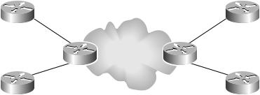
Shared router In Figure 4.26, different customers connect to the same PE. For example, Customer A1 and Customer B1 connect to the New York PE. “Shared router” really means “shared routing table.” On the PE, there is only one routing table. Security and route filtering are a pain because of the amount of management overheard required for security and routing table isolation.
F I G U R E 4 . 2 6 A shared router VPN implementation
VPN A routes |
|
|
|
VPN A routes |
||
|
|
|
|
|
|
|
|
|
|
|
VPN A routes |
|
|
|
|
|
|
VPN B routes |
|
|
Customer A1 |
|
|
Customer A2 |
|||
New York PE |
|
D.C. PE |
||||
|
|
|
|
|
|
|
|
|
VPN A routes |
|
|
|
|
|
|
VPN B routes |
|
|
|
|
|
|
|
|
|
|
|
Customer B1 |
|
|
Customer B2 |
|||
|
|
|
|
|
|
|
VPN B routes |
|
|
|
VPN B routes |
||
|
|
|
|
|
|
|
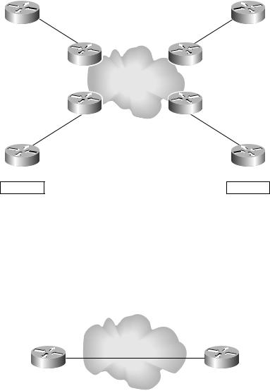
Dedicated router To get away from sharing a single routing table on a PE and all the management that is required, a service provider can provide a dedicated PE router for each VPN customer. Figure 4.27 illustrates a dedicated router implementation.
Dedicated routers offer more security but at a substantial price (a dedicated PE router for each separate VPN customer).
Copyright ©2002 SYBEX, Inc., Alameda, CA |
www.sybex.com |
|
|
|
|
|
Peer-to-Peer VPNs 143 |
|||
F I G U R E 4 . 2 7 A dedicated router VPN implementation |
|
|
|
|
||||
|
|
|
|
|
|
|
|
|
|
VPN A routes |
|
|
|
|
|
VPN A routes |
|
|
|
|
|
|
|
|
|
|
|
Customer A1 |
VPN A routes |
|
VPN A routes |
|
Customer A2 |
||
|
New York PE1 |
|
|
|
D.C. PE1 |
|||
|
New York PE2 |
|
|
|
D.C. PE2 |
|||
|
|
|
|
|
|
|
|
|
|
|
|
VPN B routes |
|
VPN B routes |
|
|
|
Customer B1
VPN B routes
Customer B2
VPN B routes
Real World Peer-to-Peer Networks
To give you an example of how peer-to-peer VPN networks look in the real world, let’s run through a quick example.
Suppose there’s a customer with a simple VPN using Frame Relay. Figure 4.28 illustrates this customer’s network.
F I G U R E 4 . 2 8 A simple VPN using Frame Relay
Frame Relay
Virtual circuits (VCs)
Site 1 |
Site 2 |
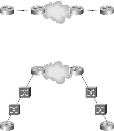
Now the customer wants a peer-to-peer VPN. Figure 4.29 illustrates the new peer-to-peer network.
Copyright ©2002 SYBEX, Inc., Alameda, CA |
www.sybex.com |
144 Chapter 4 VPNs: An Overview
F I G U R E 4 . 2 9 A simple peer-to-peer VPN
Site 1 |
PE1 |
PE2 |
Site 2 |
So far, nothing should be new. What you really need to know is that technologies such as Frame Relay, ISDN, DSL, etc. are still in use by the service provider. Figure 4.30 illustrates a real world example where Site 1 and Site 2 connect to the PE routers through Frame Relay.
F I G U R E 4 . 3 0 A real world peer-to-peer VPN network
PE1 |
PE2 |
Frame Relay |
Frame Relay |
Frame Relay |
Frame Relay |
Site 1 |
Site 2 |
Overlay VPNs Compared to
Peer-to-Peer VPNs
Overlay VPN technology has been around for a long while. Since it’s been around for so long, everyone knows how it works. In addition, the service provider and customer sites are well isolated from each other. Remember, to
Copyright ©2002 SYBEX, Inc., Alameda, CA |
www.sybex.com |
