

vk.com/club152685050Cyclic Symmetry Analysis | vk.com/id446425943
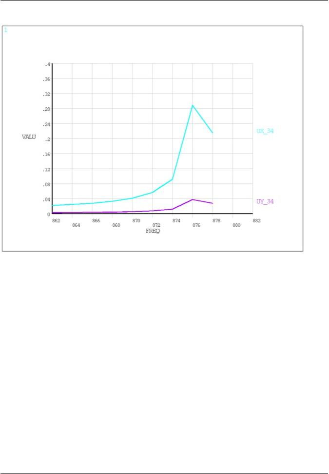
Figure 7.27: Displacement Plot as a Function of Excitation Frequency
7.8. Example Magnetic Cyclic Symmetry Analysis
This magnetic cyclic symmetry analysis uses a model of a simplified electrical machine where the model size can be reduced via cyclic boundary conditions.
7.8.1.Problem Description
7.8.2.Problem Specifications
7.8.3.Input file for the Analysis
7.8.1. Problem Description
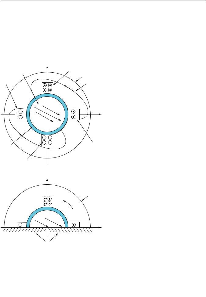
Figure 7.28: Two-Phase Electric Machine – Full Model (p. 217) shows a typical example, the full model of a 2-phase electrical machine.
In the full model, flux parallel boundary conditions can be formulated at the outer surface of the stator frame. If only phase A were excited, the magnetic flux would point in the y direction at x=0 plane; flux parallel condition could be formulated at the x=0 plane, allowing an analysis on a half model in the x>=0 space. Similarly, if only phase B were excited, the magnetic flux would have only x component
on the y=0 plane; again, flux parallel could be applied to a half model in the y>=0 plane.
Typically, however, both coils are excited, and no flux parallel conditions could be formulated over the x=0 or y=0 planes. However, due to the cyclic nature of the field, the field pattern repeats itself after 180 degrees. In particular, on the y=0 plane:
|
Release 15.0 - © SAS IP, Inc. All rights reserved. - Contains proprietary and confidential information |
216 |
of ANSYS, Inc. and its subsidiaries and affiliates. |
vk.com/club152685050 | vk.com/id446425943 |
Example Magnetic Cyclic Symmetry Analysis |
By(x) = By(-x)
A similar pattern can be observed in Figure 7.29: Two-Phase Electric Machine – Half Model (p. 217), where the flux lines (equi vector potential lines) are plotted:
Az(x) = - Az(-x)
In this example, the field has a two pole pattern. In general, there are 2p poles; the repetition would take place after 180/p degrees.
Figure 7.28: Two-Phase Electric Machine – Full Model
|
y |
Coil phase B+ |
|
|
|
Rotor |
|
|
|
|
Flux tangential BC |
Coil phase A- |
|
Stator |
|
|
|
|
|
B |
+ |
|
|
+ |
|
x |
|
|
|
|
|
B |
+ |
+ |
|
B |
|
|
+ |
+ |
Coil phase A+ |
|
|
|
Air gap |
|
|
Coil phase B- |
|
|
Figure 7.29: Two-Phase Electric Machine – Half Model
|
|
|
|
|
|
|
|
|
|
|
|
|
|
|
|
|
|
|
|
|
|
|
|
c c |
d |
|
c c w d |
|
|
|
|
|
P d c |
|
|
7.8.2. Problem Specifications
The material properties for this analysis are as follows:
Iron relative permeability: 1000
Iron electrical resistivity: 9.579E-8
Release 15.0 - © SAS IP, Inc. All rights reserved. - Contains proprietary and confidential information |
|
of ANSYS, Inc. and its subsidiaries and affiliates. |
217 |

vk.com/club152685050Cyclic Symmetry Analysis | vk.com/id446425943
Aluminum relative permeability: 1.0
Aluminum electrical resistivity: 2.65E-8
Copper relative permeability: 1.0
Copper electrical resistivity: 1.74E-8
7.8.3. Input file for the Analysis
Use this input file to perform the example magnetic cyclic symmetry analysis. This file contains the complete geometry, material properties, and solution options for the finite element model. Magnetic cyclic symmetry commands of particular interest are preceded by the comment:
!!!Apply Cylic
/title,Cyclic Symmetry Model for EMAG Analysis (Dual Coils with Iron Yoke) /com
/com ***** Quarter Symmetry Model Expanded to Half Then to Full *****
/com
/com
/com
/nopr
/out,scratch
!!! Setup Model Parameters
_geomgen=1 |
|
p=1 |
! Use for number of quarter sectors |
|
! (i.e. 1 = 1 90deg sector, 2 = 2 sectors in 90deg) |
alpha=22.5/p |
! angle up to the end of first coil |
beta=alpha+(45/p) |
! angle from coil1 to coil2 |
gamma=beta+(22.5/p) |
! angle from beginning of coil2 to end of sector |
r1=3
r2=4.5
r3=5
r4=7
r5=11
ncoil=(4*p)
i1=1
i2=2
*dim,alpha1,,ncoil
*dim,alpha2,,ncoil
*dim,current,,ncoil
*dim,coilname,string,ncoil
coilname(1) = 'coil1' coilname(2) = 'coil2' coilname(3) = 'coil3' coilname(4) = 'coil4'
*do,i,1,ncoil
alpha1(i) = -alpha + (i-1)*(90/p) alpha2(i) = alpha + (i-1)*(90/p)
*enddo
ii=0
*do,i,1,p
ii = ii + 1 current(ii) = i2 ii = ii + 1 current(ii) = i1
|
Release 15.0 - © SAS IP, Inc. All rights reserved. - Contains proprietary and confidential information |
218 |
of ANSYS, Inc. and its subsidiaries and affiliates. |

vk.com/club152685050 | vk.com/id446425943 |
Example Magnetic Cyclic Symmetry Analysis |
ii = ii + 1 current(ii) = -i2 ii = ii + 1 current(ii) = -i1
*enddo
/prep7
ET,1,13,4 |
! Use PLANE13 Elements (DOFset = UX,UY,TEMP,AZ) |
!!! Setup Model using Parameters
PCIRC,r1, ,0,alpha,
PCIRC,r1, ,0,beta
PCIRC,r1, ,0,gamma
PCIRC,r2, ,0,alpha
PCIRC,r2, ,0,beta
PCIRC,r2, ,0,gamma
PCIRC,r3, ,0,alpha
PCIRC,r3, ,0,beta
PCIRC,r3, ,0,gamma
PCIRC,r4, ,0,alpha
PCIRC,r4, ,0,beta
PCIRC,r4, ,0,gamma
PCIRC,r5, ,0,alpha
PCIRC,r5, ,0,beta
PCIRC,r5, ,0,gamma
AOVLAP,ALL
!!! Setup Material Properties
!IRON MP,MURX,1,1000 MP,RSVX,1,9.579E-8
!AL
MP,MURX,2,1
MP,RSVX,2,2.65E-8
!Copper MP,MURX,3,1 MP,RSVX,3,1.74E-8
!Air MP,MURX,4,1 MP,RSVX,4,0
!!! Setup Components and Atributes
! Iron Core
CSYS,1 ! Enter Cylindrical Mode
ASEL,S,LOC,X,0,r1
CM,Inner_Iron,AREA
AATT,1,,1,
!Al Core ASEL,S,LOC,X,r1,r2 CM,Outer_AL,AREA AATT,2,,1,
!Air Gap ASEL,S,LOC,X,r2,r3 CM,AIR,AREA AATT,4,,1
!Coil 1 ASEL,S,LOC,X,r3,r4 ASEL,R,LOC,Y,0,alpha CM,COIL1,AREA
Release 15.0 - © SAS IP, Inc. All rights reserved. - Contains proprietary and confidential information |
|
of ANSYS, Inc. and its subsidiaries and affiliates. |
219 |

vk.com/club152685050Cyclic Symmetry Analysis | vk.com/id446425943
AATT,3,,1
!Coil 2 ASEL,S,LOC,X,r3,r4 ASEL,R,LOC,Y,beta,gamma CM,COIL2,AREA AATT,3,,1
!Iron Yoke ASEL,S,LOC,X,r3,r4 ASEL,R,LOC,Y,alpha,beta ASEL,A,LOC,X,r4,r5 CM,YOKE,AREA
AATT,1,,1 ALLSEL
CSYS,0 |
! Enter Cartesian Mode |
!!! Setup and Mesh Model
MSHKEY,1
CSYS,1
LSEL,S,LOC,Y,0
LSEL,A,LOC,Y,gamma
LESIZE,ALL,,,6,,1,,,1,
CMSEL,S,Inner_Iron
AMESH,ALL
CMSEL,S,Outer_AL
AMESH,ALL
CMSEL,S,Air
AMESH,ALL
CMSEL,S,Coil1
AMESH,ALL
CMSEL,S,Coil2
AMESH,ALL
CMSEL,S,Yoke
AMESH,ALL
ALLSEL
CSYS,0
!!! Reflect Model across X-axis
!! Create HALF model from QUARTER model
arsym,x,all
/prep7 |
|
save,magtest,db |
! save half model for cyclic |
arsym,y,all |
! create full model reflecting on y axis |
nummrg,all |
|
csys,1 |
|
nsel,s,loc,x,r5 |
|
CM,extnode,NODE |
|
! Apply BFE Current loads to each coil
*do,i,1,ncoil
asel,s,loc,x,r3,r4
asel,r,loc,y,alpha1(i),alpha2(i)
esla,s
cm,coilname(i),element
bfe,all,js,,,,current(i)
*enddo
csys,0
allsel cmsel,s,extnode d,all,az,0
|
Release 15.0 - © SAS IP, Inc. All rights reserved. - Contains proprietary and confidential information |
220 |
of ANSYS, Inc. and its subsidiaries and affiliates. |

vk.com/club152685050 | vk.com/id446425943 |
Example Magnetic Cyclic Symmetry Analysis |
d,all,temp,25 allsel FINISH
/solu
/out,scratch
antype,static allsel
solve
FINISH
/post1
!!! Plot Out Result Plots plvect,b,,,,VECT,ELEM,ON,0
FINISH parsav,all /clear,nostart
resume,magtest,db ! Resume half Model parres,new
!! Delete Bottom half of model and all loading attatched to bottom nodes
/prep7
allsel nummrg,all
csys,1
nsel,s,loc,x,r5
D,all,az,0 ! AZ = 0 on outside nodes of arc D,all,temp,25
!! Define Coils on Half Model
!Coil 1 ASEL,S,LOC,X,r3,r4 ASEL,R,LOC,Y,0,alpha esla,s CM,COIL1,ELEMENT
!Coil 2 ASEL,S,LOC,X,r3,r4
ASEL,R,LOC,Y,beta,(180-beta) esla,s
CM,COIL2,ELEMENT
!Coil 3
ASEL,S,LOC,X,r3,r4 ASEL,R,LOC,Y,(180-alpha),180 esla,s
CM,COIL3,ELEMENT
!! Apply bfe loads to Half Model coils
cmsel,s,COIL1
bfe,all,js,,,,i2
cmsel,s,COIL2
bfe,all,js,,,,i1
cmsel,s,COIL3 bfe,all,js,,,,(-i2)
!!!Apply cyclic - create cyclic model with two sectors
allsel csys,0 cyclic,2
/solution
Release 15.0 - © SAS IP, Inc. All rights reserved. - Contains proprietary and confidential information |
|
of ANSYS, Inc. and its subsidiaries and affiliates. |
221 |
vk.com/club152685050Cyclic Symmetry Analysis | vk.com/id446425943
cycopt,hindex,odd |
! Odd Symmetry for half model |
solve |
|
FINISH |
|
/post1 |
|
/out |
|
!!! Plot Out Result Plots |
|
/vscale,1,1,1 |
|
plvect,b,,,,VECT,ELEM,ON,0 |
! See figure for B field plot. |
!!! Plot Out Contour Line Plot of Equipotentials plf2d
FINISH
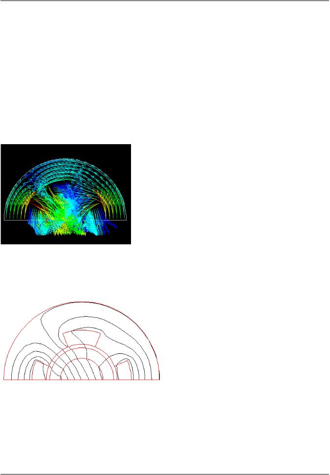
Figure 7.30: Vector Plot of Cyclic Flux Density (B) - Half Model
Figure 7.31: Contour Line Plot of Equipotentials
|
Release 15.0 - © SAS IP, Inc. All rights reserved. - Contains proprietary and confidential information |
222 |
of ANSYS, Inc. and its subsidiaries and affiliates. |