

vk.com/club152685050 | vk.com/id446425943 |
Postprocessing a Cyclic Symmetry Analysis |
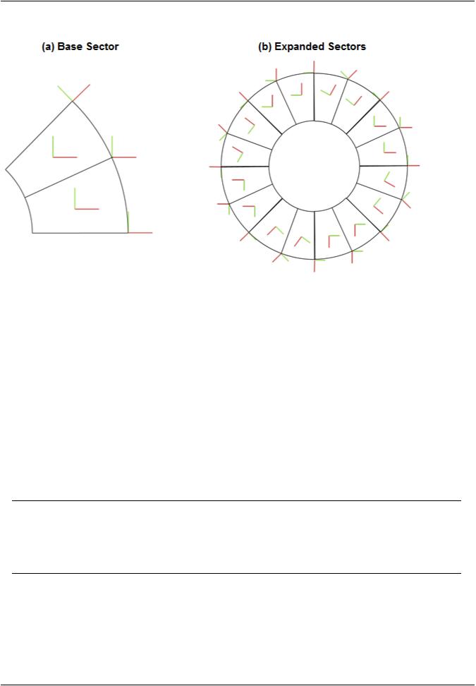
Figure 7.19: Cyclic Results Coordinate Systems withRSYS,SOLU
7.4.2. Modal Solution
A cyclic symmetry solution typically has multiple load step results depending upon the harmonic index solutions requested. The SET,LIST command will list the harmonic indices solved and the frequencies within each harmonic index. Use SET,LIST,,,,,,,ORDER to list the frequencies themselves in numerical order.
7.4.2.1. Real and Imaginary Solution Components
To transform the real and imaginary cyclic symmetry solution results to the actual structure solution, three postprocessing (/POST1) commands are available:
•/CYCEXPAND
•EXPAND
•CYCPHASE
Note
The CYCPHASE command uses full model graphics (/GRAPHICS,FULL) to compute peak values. Because of this, there may be slight differences between max/min values obtained with CYCPHASE, and those obtained via /CYCEXPAND (/GRAPHICS,POWER).
For information about /CYCEXPAND and EXPAND command usage, see Expanding the Cyclic Symmetry Solution (p. 196). For information about CYCPHASE command usage, see Phase Sweep of Repeated Eigenvector Shapes (p. 197).
Release 15.0 - © SAS IP, Inc. All rights reserved. - Contains proprietary and confidential information |
|
of ANSYS, Inc. and its subsidiaries and affiliates. |
195 |

vk.com/club152685050Cyclic Symmetry Analysis | vk.com/id446425943
7.4.2.2. Expanding the Cyclic Symmetry Solution
This section describes the capabilities of the /CYCEXPAND and EXPAND commands and explains their differences. Use the commands to expand the solution results of your cyclic symmetry analysis to the full model.
The /CYCEXPAND command does not modify the geometry, nodal displacements, or element stresses stored in the database. For more details, see Using the /CYCEXPAND Command (p. 193).
The EXPAND command offers an alternate method for displaying the results of a modal cyclic symmetry analysis. It is a specification command that causes a SET operation to transform and expand the data
it is reading before storing it in the database. If you request two or more sector repetitions, the command creates additional nodes and elements to provide space for the extra results.
After the real-space results are stored in the database, you can plot (PLESOL or PLNSOL), print (PRNSOL). You can also process them as you would those for a non-cyclic analysis, in cases where you may wish
to process results in a manner unsupported by the /CYCEXPAND command. Care should be taken in such cases as the database can become very large, negating the inherent model size advantage of a cyclic symmetry analysis.
Caution
Do not confuse the EXPAND command with /EXPAND.
7.4.2.3. Applying a Traveling Wave Animation to the Cyclic Model
After you have completed a modal cyclic symmetry analysis, you can apply an animated traveling wave to the cyclic model by issuing the ANCYC command (which uses /CYCEXPAND functionality). The traveling wave capability applies only to modal cyclic symmetry analyses. For more information, see the description of the ANCYC command in the Command Reference.
Figure 7.20: Traveling Wave Animation Example (p. 196) illustrates the ANCYC command's effect. To view the input file used to create the model shown, see Example Modal Cyclic Symmetry Analysis (p. 198).
The following demo is presented as an animated GIF. Please view online if you are reading the PDF version of the help. Interface names and other components shown in the demo may differ from those in the released product.
Figure 7.20: Traveling Wave Animation Example
|
Release 15.0 - © SAS IP, Inc. All rights reserved. - Contains proprietary and confidential information |
196 |
of ANSYS, Inc. and its subsidiaries and affiliates. |
vk.com/club152685050 | vk.com/id446425943 |
Postprocessing a Cyclic Symmetry Analysis |
7.4.2.4. Phase Sweep of Repeated Eigenvector Shapes
In a modal cyclic symmetry analysis, repeated eigenfrequencies are obtained at solutions corresponding to harmonic indices k, greater than 0 and less than N/2. The repeated modes are a consequence of the cyclically symmetric geometry of the structure or assembly being modeled by the cyclic sector.
The eigenvector shapes corresponding to the repeated eigenfrequencies are non-unique. That is, for the repeated eigenfrequencies fi = fi+1, the mode shapes corresponding to fi and fi+1 can be linearly combined to obtain a mode shape that is also a valid mode shape solution for the frequencies fi and fi+1. A valid linear combination of the eigenvectors is:
= |
+ |
+ |
(7.4) |
i |
i |
1 |
|
where,
c1 and c2 = Arbitrary constants
Ui and Ui+1 = Eigenvectors corresponding to fi and fi+1, respectively
The orientation of the combined mode shape U will be along a nodal diametral line that is neither along that of Ui nor Ui+1. Because the full structure may have stress-raising features (such as bolt holes), determining the eigenvector orientation that causes the most severe stresses, strains, or displacements on the structure or assembly is critical.
To determine the peak value of stress, strain or displacement in the full structure or assembly, it is necessary to calculate U at all possible angular orientations ϕ in the range of 0 through 360°. In the general postprocessor, the CYCPHASE command performs the computational task.
Because c1 and c2 are arbitrary constants, the CYCPHASE calculation rewrites Equation 7.4 (p. 197) as follows:
= |
φ − + |
φ |
(7.5) |
Using the cyclic symmetry expansion of Equation 7.3 (p. 193) in Equation 7.5 (p. 197), the simplified phasesweep equation that operates on the cyclic sector solution (rather on the computation-intensive fullstructure expression in Equation 7.5 (p. 197)) is:
φ = |
A |
φ − B φ |
(7.6) |
|
|
|
|
A phase sweep using the CYCPHASE command provides information about the peak values of stress, strain and/or displacement components and the corresponding phase angle values. Using the phase angle value further, you can expand the mode shape at that phase angle to construct the eigenvector shape that produces the peak stress, strain and/or displacement. The expansion expression with the phase angle used by the /CYCEXPAND command is:
 =
= 


 −
− 
 α + φ −


 −
− 
 α + φ (7.7)
where,
n = 1,2,3,...,N
Example:
To determine the eigenvector orientation that causes the highest equivalent stress, perform a phase sweep on the stress via the CYCPHASE,STRESS command. Obtain a summary of the phase sweep via
Release 15.0 - © SAS IP, Inc. All rights reserved. - Contains proprietary and confidential information |
|
of ANSYS, Inc. and its subsidiaries and affiliates. |
197 |