


vk.com/club152685050Cyclic Symmetry Analysis | vk.com/id446425943
7.2.2. Edge Component Pairs
The cyclic sector has two edges that align along the surfaces of cyclic symmetry. The edge having the algebraically lower θ in the R-θ (cylindrical) coordinate system is called the low edge and the one having the higher θ is called the high edge. The angle α between the two successive surfaces of cyclic symmetry is called the sector angle.
When setting up a cyclic symmetry analysis, the CYCLIC command defines edge components automatically, assigning them a default root name of “CYCLIC.”
Optionally, you can use the CYCLIC command to define the edges and the component names manually. If you do so, you must specify a root name for the sector lowand high-edge components (line, area,
or node components). A root name that you specify can contain up to 11 characters. The naming convention for each lowand high-edge component pair is either of the following:
name_mxxl, name_mxxh
(potentially matched node patterns)
name_uxxl, name_uxxh
(potentially unmatched node patterns)
The name value is the default (“CYCLIC”) or specified root name, and xx is the component pair ID number (sequential, starting at 01).
7.2.2.1. CYCOPT Auto Detection Tolerance Adjustments for Difficult Cases
If the CYCLIC command fails to auto-detect the edges of your cyclic sector, adjusting the ANGTOL and/or FACETOL values of the CYCOPT command may help. The most effective way to correct autodetection is usually by changing the ANGTOL value; however, for more difficult cases from FEA models you may need to change FACETOL to achieve auto detection.
When using the CYCOPT command, face tolerance, or FACETOL, automatically defaults to 15 degrees. Face tolerance applies only to auto-detection from node/element models that are already meshed, and are not solid models. The default face tolerance will accommodate most models, unless they include extreme angles or complex model geometry, both of which can cause surface nodes to be excluded. This problem, and possible solutions are illustrated in this section using the cyclic model shown in Figure 7.4: Full Cyclic Model (p. 167).
|
Release 15.0 - © SAS IP, Inc. All rights reserved. - Contains proprietary and confidential information |
166 |
of ANSYS, Inc. and its subsidiaries and affiliates. |
vk.com/club152685050 | vk.com/id446425943 |
Cyclic Modeling |
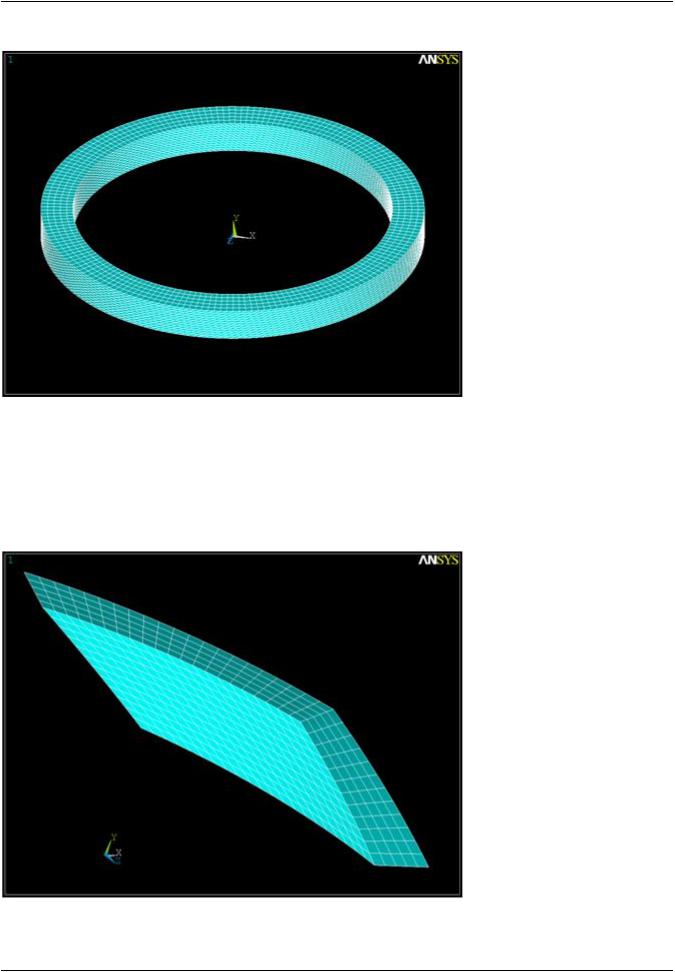
Figure 7.4: Full Cyclic Model
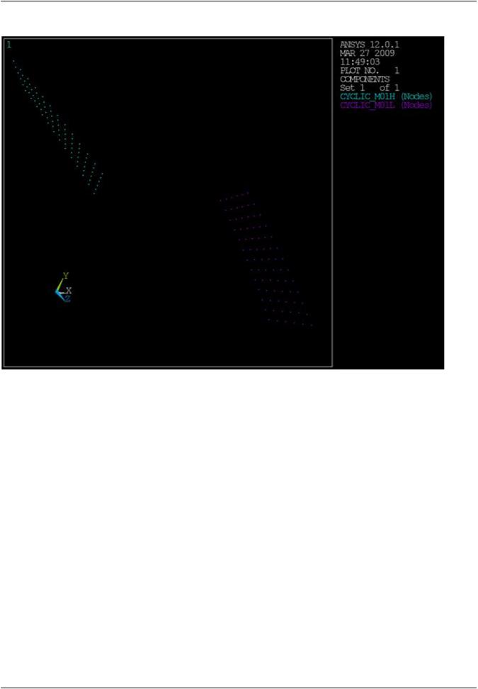
Figure 7.5: Cyclic Sector (p. 167) shows a cyclic sector from the model above. As you can see, this sector model is leaning heavily in the circumferential direction. The low and high boundaries in this figure have been auto detected correctly using the default FACETOL value of 15 deg. This successful auto
detection of these boundaries can be seen in Figure 7.6: Successful Auto Detection with Default FACETOL = 15 Deg (p. 168).
Figure 7.5: Cyclic Sector
Release 15.0 - © SAS IP, Inc. All rights reserved. - Contains proprietary and confidential information |
|
of ANSYS, Inc. and its subsidiaries and affiliates. |
167 |
vk.com/club152685050Cyclic Symmetry Analysis | vk.com/id446425943
Figure 7.6: Successful Auto Detection with DefaultFACETOL = 15 Deg
If you reset the FACETOL values in the figure above from 15 degrees to 30 degrees, auto detection fails because the logic treats the left and bottom sides of the sector as a single face, and the top and right sides as a second large face. This is because the bottom-left edge and top-right edge of this model both contain a dihedral angle greater than 150 degrees (180-30), but less than 165 degrees (18015). These large angles add to the possibility of auto-detection errors.
If you start with a model tilted more than the sector in Figure 7.6: Successful Auto Detection with Default FACETOL = 15 Deg (p. 168), it may fail at the default tolerance of 15 degrees. This may require you to reduce FACETOL to 10 or even 5 degrees to get a successful result.
A FACETOL value that is set too low can also result in failure. A FACETOL value that is too low can cause edges not to be detected along element boundaries on smooth surfaces. The valid range of FA-
CETOL is model and mesh dependent, and may be dictated by a single edge shared between 2 elements.
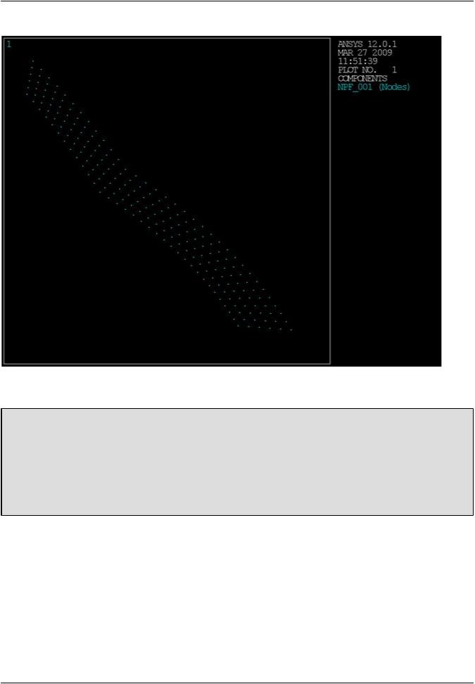
Whenever auto detect fails for an element model, save the node groups for each element face that you were working with as node components NPF_001, NPF_002, etc. for diagnostic purposes. Each node component should represent exactly one face of the cyclic sector (cyclic boundary or not).
In Figure 7.7: Auto Detection Failure Due to Large Face Tolerance (p. 169) , NPF_001 is clearly too large. As you can see from the nodes, the group has leaked across the lower left edge. This indicates that FACETOL is too large for the given dihedral angle.
|
Release 15.0 - © SAS IP, Inc. All rights reserved. - Contains proprietary and confidential information |
168 |
of ANSYS, Inc. and its subsidiaries and affiliates. |
vk.com/club152685050 | vk.com/id446425943 |
Cyclic Modeling |
Figure 7.7: Auto Detection Failure Due to Large Face Tolerance |
|
7.2.2.2. Identical vs. Dissimilar Edge Node Patterns
Automated Matching
The AMESH and VMESH commands perform automated matching. All other meshing-operation commands (for example, VSWEEP) do not.
If you specify a meshing operation other than AMESH or VMESH, ensure that node and element face patterns match, if desired. The CYCLIC command output indicates whether each edge-com- ponent pair has or can produce a matching node pair.
To ensure the most accurate solution, it is preferable to have identical node and element face patterns on the low and high edges of the cyclic sector. If you issue the CYCLIC command before meshing the cyclic sector (via the AMESH or VMESH command only), the mesh will have identical node and element face patterns on the low and high edges if possible. In this case, all entities must be meshed together using one meshing command.
The program allows dissimilar node patterns on the low and high edges of the cyclic sector, useful when you have only finite-element meshes for your model but not the geometry data necessary to
remesh it to obtain identical node patterns. In such cases, it is possible to obtain solution (SOLVE) results, although perhaps at the expense of accuracy. A warning message appears because results may be degraded near the cyclic sector edges.
Release 15.0 - © SAS IP, Inc. All rights reserved. - Contains proprietary and confidential information |
|
of ANSYS, Inc. and its subsidiaries and affiliates. |
169 |