

Fiber_Optics_Physics_Technology
.pdf8.5. Elements for Polarization Manipulation |
125 |
mirrored surfaces
d air gap
Transmissivity |
|
|
|
|
1 |
|
|
|
|
|
|
|
|
24% |
|
|
|
|
74% |
0 |
|
|
|
97% |
|
|
|
|
|
0 |
1/2 |
1 |
3/2 |
d /λ |
air gap width
Figure 8.7: Two fibers have their end faces coated with a partially reflecting layer to give a reflectivity R and are then combined into a Fabry–Perot interferometer. Its transmissivity is shown here for three selected values of R. The curves are valid for a very small gap; if the gap is wider than a couple of wavelengths, additional loss arises from the widening of the light exit cone and the beginning curvature of the wavefronts. Also, short coherence length light will wash out the fringes. Compare with Fig. 8.5 where R ≈ 0.035 was assumed.
mirrors in fiber lasers (see Sect. 9.7.2). A further development are “chirped” gratings which have a sliding grating period and which find use as band filters.
8.5Elements for Polarization Manipulation
8.5.1Polarization Adjusters
It is well known that a given state of polarization can be translated into some other state of the same degree of polarization by inserting a suitable retardation plate (birefringent plate) into the beam. The most common plates are half-wave plates (λ/2 plates) with a retardation of one half wavelength which allow, e.g., to rotate the plane of polarization of a linearly polarized light beam by any
126 |
Chapter 8. Components for Fiber Technology |
angle, and quarter-wave plates (λ/4 plates) which can transform, e.g., linear polarization into circular polarization or the other way round. Such birefringent elements can also be built in all-fiber technology.
A fiber loop, by virtue of the bending, is birefringent, and its birefringence is given by [93]
n = b |
|
r |
2 |
, |
(8.1) |
|
|||||
|
|
R |
|
|
|
where b = 0.133 is an empirical constant, r the fiber radius, and R the bend radius. This birefringence provides a phase di erence between the orthogonal polarization components parallel and perpendicular to the plane of the loop, given by
ϕ = k z = |
2π n |
2πRW |
(8.2) |
|
λ |
||||
|
|
|
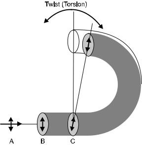
with W the number of turns. To understand the e ect one can mentally decompose the state of polarization of the incoming light into the component along the fast axis (in the loop plane) and that along the slow axis (parallel to the loop’s axis) (see Fig. 8.8). This allows to follow both components individually, putting them together after the loop produces the change of polarization state. By rotating the loop around the axis given by the incoming fiber, one changes the projection and thus the change of polarization state. The e ect is equivalent to the rotation of a conventional wave plate around the beam direction.
Figure 8.8: Torsion of a fiber rotates the birefringent axes. If, e.g., the incoming light is linearly polarized as A, then it oscillates in the fast axis of the nontwisted fiber (B) and the state of polarization is maintained. If the fiber gets twisted, though, the polarization plane is at an angle with the resulting axis (C); then the state of polarization will evolve upon further propagation in the loop.
8.5. Elements for Polarization Manipulation |
127 |
|||||||||||||
|
|
|
|
|
|
|
|
|
|
|
|
|
|
|
|
|
|
|
|
|
|
|
|
|
|
|
|
|
|
|
|
|
|
|
|
|
|
|
|
|
|
|
|
|
|
|
|
|
|
|
|
|
|
|
|
|
|
|
|
|
|
|
|
|
|
|
|
|
|
|
|
|
|
|
|
|
|
|
|
|
|
|
|
|
|
|
|
|
|
|
|
|
|
|
|
|
|
|
|
|
|
|
|
|
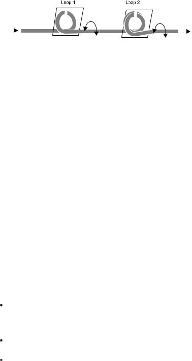
Figure 8.9: Fiber loops as polarization controllers. The individual loops can be designed as half-wave or quarter-wave elements and are adjusted by rotation (arrows). For a realization see the picture on p. 85.
Specifically, this is what one finds: If a quarter wave of retardation is desired and if one chooses W = 1 (a single turn), then
ϕ = |
π |
R = |
8πbr2 |
(8.3) |
||
|
|
|
. |
|||
2 |
λ |
|||||
At λ = 1.5 μm and for a fiber with 2r = |
125 μm, |
a single loop of radius |
||||
R = 8.7 mm constitutes a quarter-wave plate. Equations (8.2) and (8.3) are only approximate because as the loops are rotated there is also some circular birefringence generated which counteracts the linear birefringence. To obtain a universally useful polarization controller one takes two or, more often, three loops with diameters on the order of a few centimeters, which may have a single, then two, and a single turn again to form a quarter-wave, a half-wave, and another quarter-wave plate. The loops are hinged so that they can be rotated easily (Fig. 8.9). Such a device acts as a polarization controller and is capable of transforming any incoming state into any outgoing state of polarization [93].
This construction is helpful in the laboratory but requires mechanically moving parts. It is therefore not very suitable for automatic polarization control. For the latter, a concept is preferred which generates birefringence by squeezing the fiber by mechanical force applied transversally. In a practical design, the fiber is squeezed at several positions in di erent directions by piezoceramic actuators [140].
8.5.2Polarizers
A polarizer creates losses selectively for one of two possible orthogonal states of polarization. Three technical realizations are well known in optics.
Glass plates sit in the beam at an angle; the two linearly polarized components (perpendicular and parallel to the entrance plane) are reflected di erently and thus get attenuated di erently in transmission. The contrast is maximized by choosing Brewster’s angle.
In birefringent crystals like calcite, both polarization components are spatially separated.
Dichroitic films contain chain molecules in which electrons can move freely along the chain but not transversally. All molecules have the same orientation. That part of the light that is polarized parallel to the chains is absorbed so that only the orthogonal state of polarization is transmitted.

128 |
Chapter 8. Components for Fiber Technology |
In order to make a fiber-optic polarizer, one can insert a slab of dichroitic material in a gap in the fiber. Alternatively, one can polish down a fiber from the side until its cross-section has the form of the letter D and the core is nearly exposed just beneath the flat surface. If the flat surface is then coated with metal, one obtains polarization-dependent losses.
8.6Direction-Dependent Devices
8.6.1Isolators
Isolators are well known in conventional bulk optics and play a role in laser technology. These are devices which let light pass through in one direction, but block it in the opposite direction. They are also called optical diodes.
Optical diodes rely on the Faraday e ect, the rotation of the plane of polarization of linearly polarized light in a material subject to an external longitudinal magnetic field. The physical mechanism is based on the splitting of atomic energy levels into Zeeman substates due to the magnetic field; this yields a circular birefringence. The resulting angle of rotation of the plane of polarization is given, assuming a homogenous magnetic field, by
= V HL , |
(8.4) |
where H is the magnetic field strength and L the length of the light path through the material. V is Verdet’s constant.2 This material constant has units of rad/(m A/m) = rad A−1. Since in most instances nonmagnetic materials are considered, often Eq. (8.4) is written using B instead of H; then, units are rad/(T m). Verdet’s constant depends on wavelength; according to classical theory it is given by
V = |
e |
|
λ |
dn |
, |
(8.5) |
|
2mec |
dλ |
||||||
|
|
|
|
||||
where e is the elementary charge and me the electron mass. The table shows selected typical values of V ; for a measurement across the entire visible range for fused silica (Suprasil), see [153].
Material |
Wavelength |
Verdet’s constant, |
|||
|
(λ/nm) |
V / |
|
rad |
|
|
|
||||
|
|
| | |
|
T m |
|
Water |
632 |
|
3.8 |
||
Light flint glass |
589 |
|
9 |
||
Heavy flint glass |
589 |
|
20 |
||
Fused silica |
589 |
|
4.8 |
||
Fused silica |
632 |
|
3.7 |
||
TGG |
632 |
|
134 |
||
TGG |
1,064 |
|
40 |
||
YIG |
1,310 |
|
2,200 |
||
YIG |
1,550 |
|
1,700 |
||
|
|
|
|
|
|
2Marcel Emile Verdet 1824–1866.
8.6. Direction-Dependent Devices |
129 |
In the context of practical components, it is not only Verdet’s constant that is relevant, but also the ratio of this constant and the optical loss at the operational wavelength. For visible light, it turns out that TGG (terbium gallium garnet Tb3Ga5O12) is a useful material. In the near infrared, YIG (yttrium iron garnet Y3Fe5O12) is important. Using YIG and a powerful permanent magnet (e.g., a samarium–cobalt type), path lengths of a few millimeters su ce to obtain a rotation of = 45◦. In the interest of long-term stability, one chooses the magnetic field strength high enough to drive the material into magnetic saturation. That typically happens at B ≈ 1 T, in the case of YIG at 0.178 T. Then the rotational angle becomes independent of fluctuations of the magnetic field strength.
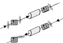
If one places one polarizer each before and after the Faraday rotator and sets their angle at 45◦ relative to each other, light can pass with minimal loss (in principle, lossless; in practice, often under 1 dB). Light propagating in the opposite direction is projected onto the 45◦ direction at the rear polarizer, is rotated by another 45◦, and arrives at the front polarizer with a total rotation of 90◦ so that it is perfectly blocked (Fig. 8.10). In practical devices the blocking is not perfect; one obtains attenuations around 30 dB, in stark contrast to the forward attenuation of ≈1 dB (Fig. 8.11).
Occasionally, the fiber itself has been used as a Faraday rotator, in order to make an all-fiber isolator [138]. Unfortunately, Verdet’s constant for fused silica is quite small so that extremely powerful (bulky, power-hungry, expensive) magnets are required. Even with superconducting magnets, one still needs to use many meters of fiber to obtain a rotation angle of 45◦. This is why in practical devices, almost always TGG or YIG is used.
There is a distinction between polarizing and polarization-independent isolators. The former are built as just described. Polarization-independent isolators first split the incoming light with birefringent polarizers into two polarization
Forward direction: A B
B
Pol 0o
A
A Pol 0o
 B
B
YIG |
Pol 45o |
|
B
YIG |
Pol 45o |
|
Backward direction: B A
A
Figure 8.10: Principle of an optical isolator based on the Faraday e ect: As linearly polarized light in 0◦ orientation passes in forward direction (A → B), it can pass through both polarizers without attenuation because they have just the right position. Backtraveling light (B → A) may be partially blocked by the rear polarizer, but inasmuch as it passes, it is rotated further and hits the front polarizer at 90◦ polarization orientation so that it is blocked there.
130 |
Chapter 8. Components for Fiber Technology |
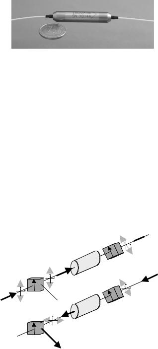
Figure 8.11: An optical isolator. It comes with two fibers attached, known as “pigtails”. The engraved arrow indicates the forward direction. A 1 Euro coin is shown for size comparison.
components. These components are then sent through the isolator on parallel but separate paths; each is rotated. Finally both components are recombined. The result is an optical diode which is “transparent” to any forward light, but blocks any backtraveling light, in full independence of its state of polarization.
8.6.2Circulators
Circulators are well-known devices in microwave engineering and have been introduced recently to fiber optics. These are multiport components (at least three “ports”). Each port can serve as an input or an output for signals. A signal launched into port 1 appears as an output at port 2, a signal launched into port 2 appears as an output at port 3, and so on – in the ideal case with cyclic permutation.
An optical circulator is based on an optical isolator (Fig. 8.12). The only modification is that the front polarizer is replaced with a version which acts as a polarizing beam splitter. The backtraveling beam is then not absorbed
Forward direction: A B
B
Pol 0o
A C
A Pol 0o
C
 B
B
YIG |
Pol 45o |
|
B
YIG |
Pol 45o |
|
Backward direction: B C
C
Figure 8.12: An optical circulator conveys signals in the directions A → B and
B → C.
8.7. Couplers |
131 |
(eliminated) but directed to an additional output, the third port where another fiber is attached. This way one obtains a three-port circulator with the functions A → B and B → C. This already su ces for a variety of useful applications. A typical example is the combination with a fiber-Bragg grating (see Sect. 9.7.2). Ports A and C are placed in the signal path; the grating is attached at port B. Fiber-Bragg gratings, which are band reject filters by their nature, are thus converted into band-pass filters which can be used to filter out a single wavelength from a wide spectrum.
8.7Couplers
There would be no way to set up a network of fiber-optic links without having the possibility to branch between several fibers. Often it is required that a signal be split into two fibers, or two signals from two fibers are to be combined into one fiber. The same goes for larger numbers of fibers.
8.7.1Power Splitting/Combining Couplers
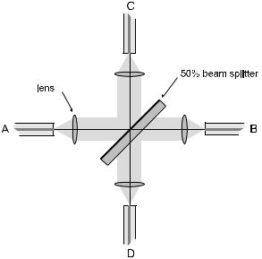
The simplest case of coupling is shown schematically in Fig. 8.13. Such a coupler can be made of discrete bulk optical elements, but is neither practical, cost- e ective, nor lossless.
Fortunately one can obtain nearly the same functionality in an all-fiber concept. Two fibers are brought together side by side over a length of a few
Figure 8.13: A discrete fiber coupler connects four fibers with the help of four collimation lenses and a beam splitter of, e.g., 50% reflection. However, such a setup requires delicate adjustments and has a rather large footprint; therefore, it is not of practical relevance. We show it solely to demonstrate the concept.
132 |
Chapter 8. Components for Fiber Technology |
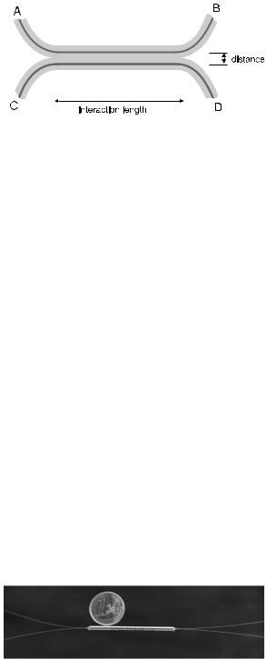
Figure 8.14: Construction of a fused fiber coupler. Two fibers are fused together over a certain well-defined length such that both cores are at a well-defined mutual distance. The distance sets the coupling coe cient of the modes; in combination with the interaction length, the branching ratio is defined. The power of a signal which is launched at A is split between B and D according to the branching ratio, etc.
centimeters (Fig. 8.14). Then both are fused together by heating. The modes in each fiber penetrate into the cladding as we have seen; in the fused coupler, the mode of one fiber has a nonvanishing spatial overlap with the mode of the other fiber. This implies that they are coupled to a certain degree. When part of the energy guided in one fiber can make the transfer to the other fiber, in that second fiber one obtains a buildup of power – accompanied by a corresponding reduction of power in the first fiber, of course. Let us consider a symmetric coupler (two like fibers) in which the phases of the wave in both fibers evolve in the same way. Then, the powers as a function of common path length z evolve as
P1 |
|
cos2(κz), |
(8.6) |
P2 |
|
sin2(κz), |
(8.7) |
where the coupling coe cient κ is sensitively dependent on the spatial distance of both fiber cores. By judicious choice of coupling coe cient and interaction length, one can tune the branching ratio of the coupler to virtually any desired value; 0% does not make much sense, but 100% is possible; more useful are values in between. Very often a 50:50 branching ratio is required. In that case there is a 3-dB attenuation for each direction so that this case is called a 3-dB coupler. Also, 10:90 branching ratio couplers (10 dB couplers) and some other values are employed (Fig. 8.15).
In an alternate procedure, two fibers are polished down from the side until the (initially circular) cross-section acquires the shape of the letter D. Then, the
Figure 8.15: A typical fused fiber coupler. It comes with four pigtails.
8.7. Couplers |
133 |
||||||||||||||
|
|
|
|
|
|
|
|
|
|
|
|
|
|
|
|
|
|
|
|
|
|
|
|
|
|
|
|
|
|
|
|
|
|
|
|
|
|
|
|
|
|
|
|
|
|
|
|
|
|
|
|
|
|
|
|
|
|
|
|
|
|
|
|
|
|
|
|
|
|
|
|
|
|
|
|
|
|
|
|
|
|
|
|
|
|
|
|
|
|
|
|
|
|
|
|
|
|
|
|
|
|
|
|
|
|
|
|
|
|
|
|
|
|
|
|
|
|
|
|
|
|
|
|
|
|
|
|
|
|
|
|
|
|
|
|
|
|
|
|
|
|
|
|
|
|
|
|
|
|
|
|
|
|
|
|
|
|
|
|
|
|
|
|
|
|
|
|
|
|
|
|
|
|
|
|
|
|
|
|
|
|
|
|
|
|
|
|
|
|
|
|
|
|
|
|
|
|
|
|
|
|
|
|
|
|
|
|
|
|
|
|
|
|
|
|
|
|
|
|
|
|
|
|
|
|
|
|
|
|
|
|
|
|
|
|
|
|
|
|
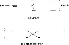
Figure 8.16: In a four-way splitter made from 3-dB couplers, each output presents one fourth of the input power. If inputs and outputs switch their roles, one obtains a four-way combiner which presents the sum of four inputs. A 4-to-4 coupler made from 3-dB couplers presents one fourth of the sum of four inputs at each of its four outputs. This principle can be extended to practically any arbitrary number of inputs and outputs.
flat sides are brought into contact and adjusted; this gives a fiber coupler with a tunable coupling ratio.
In either case couplers are four-port devices. If only three ports are used, the device acts as a splitter or as a combiner. One can add more devices in order to split/combine among more channels: E.g., three couplers allow to make a 1-to-4 splitter (four-way splitter); four couplers can be combined into a 4-to-4 coupler (4-by-4 broadcast star) (see Fig. 8.16).
In the context of photonic components, there is also a technology of optical components integrated on a microchip. When the application demands that light is coupled out of a fiber and into a photonic chip anyway, it may make sense to include the couplers on-chip.
8.7.2Wavelength-Dependent Couplers
Quite often, it is desired to split or combine various signals in fibers not all in the same way but according to their wavelength. This is the prerequisite for wavelength division multiplexing (WDM, see Sect. 11.1.5) which in turn is the basis for utilizing the enormous bandwidth provided by the fiber (25 THz in the third window) to anything more than a ridiculously small fraction.
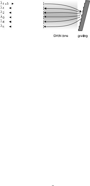
Such wavelength-dependent couplers (WDM couplers) can be made in principle with bulk optics. Figure 8.17 shows the idea for the case of a 5-to-1 WDM coupler using a di raction grating and a GRIN lens (GRIN = gradient index). In practical devices all-fiber versions are desirable. There are constructions using the wavelength dependence of the branching ratio in fused fiber couplers; this may be augmented with grating structures. There are also constructions using interference filters.
134 |
|
|
|
Chapter 8. Components for Fiber Technology |
||
|
|
|
|
|
|
|
|
|
|
|
|
|
|
|
|
|
|
|
|
|
|
|
|
|
|
|
|
|
|
|
|
|
|
|
|
|
|
|
|
|
|
|
|
|
|
|
|
|
|
|
|
|
|
|
|
|
|
|
|
|
|
|
|
|
|
|
|
|
|
|
|
|
|
|
|
|
|
|
|
|
|
|
|
|
|
|
|
|
|
|
n


Figure 8.17: Basic idea of a wavelength-dependent coupler (WDM coupler) in bulk optics using a di raction grating. The acronym GRIN is for gradient index; GRIN lenses are o ered commercially. In this example, five wavelengths from an input fiber are split to as many output fibers. Of course, the direction can be reversed, and one obtains a five-way combiner.
8.8Optical Amplifiers
Signal power is lost in long pieces of fiber; more is lost in couplers. Often it is required to make up for the losses by amplifying the optical signals. The conventional technology, used until a couple of years ago, relied on so-called “repeaters” in which the optical signal was converted into an electronic signal, then was amplified and possibly reshaped by electronic means, and finally was converted back to an optical format. This is not only quite involved; it also creates a bottleneck for the data rates that can be transmitted over an optical fiber. The theoretically available bandwidth of the fiber of tens of terahertz would be reduced to whatever can be handled by electronics, which is perhaps 10 GHz. One does not easily give up three orders of magnitude of opportunity!
Fortunately enough, there are also all-optical amplifiers. They are subject to the same constraints as any other amplifier: there is no amplification without noise. Any amplifier adds some extra noise to the signal, and part of this extra noise is unavoidable due to fundamental physical reasons. The origin of that contribution can be traced back to Heisenberg’s uncertainty relation of quantum mechanics [66] as follows.
The uncertainty relation
Et ≥ /2
can also be interpreted as
n φ ≥ 12 ,
where n = E/( ω) is the photon number and φ = ωt is the phase of the light wave.
In a (linear) amplifier, the gain factor G represents the ratio of output signal power to input signal power. An ideal amplifier would just multiply the photon number such that each input photon would produce exactly G output photons. In this ideal case, there would be no change to the phase, except for a trivial overall shift φ0 due to the transit time. Then, an input signal with photon number nin would produce an output with nout = Gnin. φin would be converted
to φout = φin + φ0.