

Fiber_Optics_Physics_Technology
.pdf198 |
|
|
|
|
|
|
|
|
|
|
|
|
|
|
|
Chapter 10. A Survey of Nonlinear Processes |
|||||||||||||||||||||||||||||
|
|
|
|
|
|
|
|
|
|
|
|
|
|
|
|
|
|
|
|
|
|
|
|
|
|
|
|
|
|
|
|
|
|
|
|
|
|
|
|
|
|
|
|
|
|
|
|
|
|
|
|
|
|
|
|
|
|
|
|
|
|
|
|
|
|
|
|
|
|
|
|
|
|
|
|
|
|
|
|
|
|
|
|
|
|
|
|
|
|
|
|
|
|
|
|
|
|
|
|
|
|
|
|
|
|
|
|
|
|
|
|
|
|
|
|
|
|
|
|
|
|
|
|
|
|
|
|
|
|
|
|
|
|
|
|
|
|
|
|
|
|
|
|
|
|
|
|
|
|
|
|
|
|
|
|
|
|
|
|
|
|
|
|
|
|
|
|
|
|
|
|
|
|
|
|
|
|
|
|
|
|
|
|
|
|
|
|
|
|
|
|
|
|
|
|
|
|
|
|
|
|
|
|
|
|
|
|
|
|
|
|
|
|
|
|
|
|
|
|
|
|
|
|
|
|
|
|
|
|
|
|
|
|
|
|
|
|
|
|
|
|
|
|
|
|
|
|
|
|
|
|
|
|
|
|
|
|
|
|
|
|
|
|
|
|
|
|
|
|
|
|
|
|
|
|
|
|
|
|
|
|
|
|
|
|
|
|
|
|
|
|
|
|
|
|
|
|
|
|
|
|
|
|
|
|
|
|
|
|
|
|
|
|
|
|
|
|
|
|
|
|
|
|
|
|
|
|
|
|
|
|
|
|
|
|
|
|
|
|
|
|
|
|
|
|
|
|
|
|
|
|
|
|
|
|
|
|
|
|
|
|
|
|
|
|
|
|
|
|
|
|
|
|
|
|
|
|
|
|
|
|
|
|
|
|
|
|
|
|
|
|
|
|
|
|
|
|
|
|
|
|
|
|
|
|
|
|
|
|
|
|
|
|
|
|
|
|
|
|
|
|
|
|
|
|
|
|
|
|
|
|
|
|
|
|
|
|
|
|
|
|
|
|
|
|
|
|
|
|
|
|
|
|
|
|
|
|
|
|
|
|
|
|
|
|
|
|
|
|
|
|
|
|
|
|
|
|
|
|
|
|
|
|
|
|
|
|
|
|
|
|
|
|
|
|
|
|
|
|
|
|
|
|
|
|
|
|
|
|
|
|
|
|
|
|
|
|
|
|
|
|
|
|
|
|
|
|
|
|
|
|
|
|
|
|
|
|
|
|
|
|
|
|
|
|
|
|
|
|
|
|
|
|
|
|
|
|
|
|
|
|
|
|
|
|
|
|
|
|
|
|
|
|
|
|
|
|
|
|
|
|
|
|
|
|
|
|
|
|
|
|
|
|
|
|
|
|
|
|
|
|
|
|
|
|
|
|
|
|
|
|
|
|
|
|
|
|
|
|
|
|
|
|
|
|
|
|
|
|
|
|
|
|
|
|
|
|
|
|
|
|
|
|
|
|
|
|
|
|
|
|
|
|
|
|
|
|
|
|
|
|
|
|
|
|
|
|
|
|
|
|
|
|
|
|
|
|
|
|
|
|
|
|
|
|
|
|
|
|
|
|
|
|
|
|
|
|
|
|
|
|
|
|
|
|
|
|
|
|
|
|
|
|
|
|
|
|
|
|
|
|
|
|
|
|
|
|
|
|
|
|
|
|
|
|
|
|
|
|
|
|
|
|
|
|
|
|
|
|
|
|
|
|
|
|
|
|
|
|
|
|
|
|
|
|
|
|
|
|
|
|
|
|
|
|
|
|
|
|
|
|
|
|
|
|
|
|
|
|
|
|
|
|
|
|
|
|
|
|
|
|
|
|
|
|
|
|
|
|
|
|
|
|
|
|
|
|
|
|
|
|
|
|
|
|
|
|
|
|
|
|
|
|
|
|
|
|
|
|
|
|
|
|
|
|
|
|
|
|
|
|
|
|
|
|
|
|
|
|
|
|
|
|
|
|
|
|
|
|
|
|
|
|
|
|
|
|
|
|
|
|
|
|
|
|
|
|
|
|
|
|
|
|
|
|
|
|
|
|
|
|
|
|
|
|
|
|
|
|
|
|
|
|
|
|
|
|
|
|
|
|
|
|
|
|
|
|
|
|
|
|
|
|
|
|
|
|
|
|
|
|
|
|
|
|
|
|
|
|
|
|
|
|
|
|
|
|
|
|
|
|
|
|
|
|
|
|
|
|
|
|
|
|
|
|
|
|
|
|
|
|
|
|
|
|
|
|
|
|
|
|
|
|
|
|
|
|
|
|
|
|
|
|
|
|
|
|
|
|
|
|
|
|
|
|
|
|
|
|
|
|
|
|
|
|
|
|
|
|
|
|
|
|
|
|
|
|
|
|
|
|
|
|
|
|
|
|
|
|
|
|
|
|
|
|
|
|
|
|
|
|
|
|
|
|
|
|
|
|
|
|
|
|
|
|
|
|
|
|
|
|
|
|
|
|
|
|
|
|
|
|
|
|
|
|
|
|
|
|
|
|
|
|
|
|
|
|
|
|
|
|
|
|
|
|
|
|
|
|
|
|
|
|
|
|
|
|
|
|
|
|
|
|
|
|
|
|
|
|
|
|
|
|
|
|
|
|
|
|
|
|
|
|
|
|
|
|
|
|
|
|
|
|
|
|
|
|
|
|
|
|
|
|
|
|
|
|
|
|
|
|
|
|
|
|
|
|
|
|
|
|
|
|
|
|
|
|
|
|
|
|
|
|
|
|
|
|
|
|
|
|
|
|
|
|
|
|
|
|
|
|
|
|
|
|
|
|
|
|
|
|
|
|
|
|
|
|
|
|
|
|
|
|
|
|
|
|
|
|
|
|
|
|
|
|
|
|
|
|
|
|
|
|
|
|
|
|
|
|
|
|
|
|
|
|
|
|
|
|
|
|
|
|
|
|
|
|
|
|
|
|
|
|
|
|
|
|
|
|
|
|
|
|
|
|
|
|
|
|
|
|
|
|
|
|
|
|
|
|
|
|
|
|
|
|
|
|
|
|
|
|
|
|
|
|
|
|
|
|
|
|
|
|
|
|
|
|
|
|
|
|
|
|
|
|
|
|
|
|
|
|
|
|
|
|
|
|
|
|
|
|
|
|
|
|
|
|
|
|
|
|
|
|
|
|
|
|
|
|
|
|
|
|
|
|
|
|
|
|
|
|
|
|
|
|
|
|
|
|
|
|
|
|
|
|
|
|
|
|
|
|
|
|
|
|
|
|
|
|
|
|
|
|
|
|
|
|
|
|
|
|
|
|
|
|
|
|
|
|
|
|
|
|
|
|
|
|
|
|
|
|
|
|
|
|
|
|
|
|
|
|
|
|
|
|
|
|
|
|
|
|
|
|
|
|
|
|
|
|
|
|
|
|
|
|
|
|
|
|
|
|
|
|
|
|
|
|
|
|
|
|
|
|
|
|
|
|
|
|
|
|
|
|
|
|
|
|
|
|
|
|
|
|
|
|
|
|
|
|
|
|
|
|
|
|
|
|
|
|
|
|
|
|
|
|
|
|
|
|
|
|
|
|
|
|
|
|
|
|
|
|
|
|
|
|
|
|
|
|
|
|
|
|
|
|
|
|
|
|
|
|
|
|
|
|
|
|
|
|
|
|
|
|
|
|
|
|
|
|
|
|
|
|
|
|
|
|
|
|
|
|
|
|
|
|
|
|
|
|
|
|
|
|
|
|
|
|
|
|
|
|
|
|
|
|
|
|
|
|
|
|
|
|
|
|
Figure 10.8: Top: When a light pulse is amplified to very high energy, excessive peak powers may damage the gain medium. Bottom: This is circumvented by broadening of the pulses with a dispersive element prior to amplification, and a restoration of the initial pulse width with an oppositely dispersive element after amplification. As dispersive elements, either fibers as in Fig. 10.5 or gratings can be used; for the compression gratings are usually preferred.
in the central section of the pulse, and the temporal profile also approximates a rectangular. Both the leading and trailing slopes are fairly abrupt.
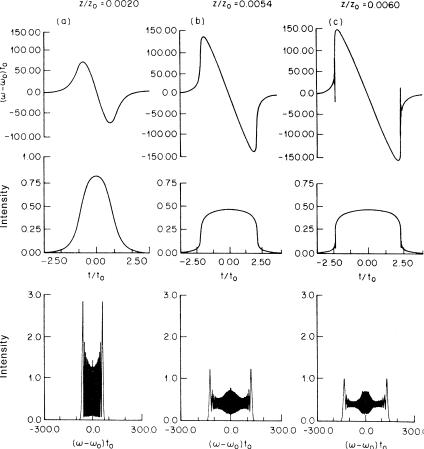
If one then keeps increasing the amount of self-phase modulation by increasing the power, there is a phenomenon called “optical wave breaking” [156] (Fig. 10.9). The portion of the pulse with the highest frequency is delayed so that it falls behind the background in the far pulse wings. At the same time,
10.2. Anomalous Dispersion |
199 |
Figure 10.9: Optical wave breaking. Top row : Evolution of the instantaneous frequency profile. There is a considerable nearly linear chirp. Center row : Evolution of the power profile. The pulse shape becomes nearly rectangular. Bottom row : The corresponding power spectra. After su ciently long propagation (right column) the wave breaks; interference fringes arise. From [156] with kind permission.
the part with the lowest frequency passes the background. That is, at the positions of the slopes the pulse “folds over” and interference phenomena arise [131]. Then oscillations appear in the wings of the temporal profile and in the spectral profile as well.
10.2Anomalous Dispersion
10.2.1Modulational Instability
We have seen in Sect. 9.4.1 that noise or tiny perturbations are subject to gain when the dispersion is anomalous and that the gain prefers certain frequencies
200 |
Chapter 10. A Survey of Nonlinear Processes |
Figure 10.10: The first observation of terahertz signals generated by modulational instability [152]. A sequence of 100 ps pulses from a Nd:YAG laser with an average power of 7.1 W is launched into a fiber of 1 km length. The figure shows power spectra of the pulse sequence at the fiber input (top) and at the fiber output (bottom). The newly generated sidebands, indicative of the modulation, are separated from the seed by 2.6 nm or ca. 450 GHz. From [153] with kind permission.
(typically on the order of 1 THz). This gain can be utilized for the generation of signals in its preferred frequency range. This comes in handy because it is not trivial to generate signals at frequencies around 1 THz; there are not many alternative methods. Figure 10.10 shows the first experimental proof that modulational instability (MI) sidebands grow from noise; in this example an oscillation of ca. 450 GHz was generated [152]. In fiber lasers one can now generate continuous oscillation of such sidebands, at least in principle [49].
10.2.2Fundamental Solitons
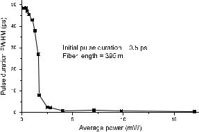
Solitons exist due to the simultaneous presence of both group velocity dispersion and Kerr nonlinearity. This can be tested by a very simple experiment: Pulses of a given duration (in this example, 560 fs) and wavelength (here, 1.5 μm) are sent through a variable attenuator into a fiber (Fig. 10.11). At the distal fiber end pulse shape and duration are monitored. As long as the power remains weak, nonlinearity does not yet play any role. Due to dispersion the pulses will broaden out, here to ca. 50 ps, which is a hundred times their initial width. As
10.2. Anomalous Dispersion |
201 |
Figure 10.11: Observation of pulse broadening by dispersion and pulse compression by nonlinearity, and the equilibrium of the two. A sequence of light pulses with an initial width of 0.5 ps is sent through a 395-m long fiber. At low power the pulses broaden out dispersively to ca. 50 ps. As the power is increased, nonlinearity counteracts dispersion and mitigates the broadening. At ca. 6 mW average power, the initial pulse width and shape are reproduced at the fiber end; indeed this is the power at which for the parameters of the fiber used here, the fundamental soliton is expected.
power is gradually increased, the pulse duration at the fiber end is significantly reduced. When ca. 6 mW average power is reached, the initial pulse shape is faithfully reproduced at the fiber end. This is the power level at which the pulse propagates without any change of shape. We have found the fundamental soliton! Its pulse shape is stable. Actually, it is stable even in the sense that mild deviations from the right shape will automatically be reduced.
If the power is further increased, the pulse undergoes a net compression; the dispersive broadening is overcompensated. But the pulse duration does not fall monotonously. This is particularly clear where the fiber length happens to be an integer multiple of z0: Then, at power levels equal to 4, 9, 16, etc. times the fundamental soliton power, the initial pulse duration is reproduced again. This repetition is of course due to higher-order solitons, but it is di cult to observe this cleanly because a multitude of e ects gets in the way of an exact reproduction of the initial shape. On the other hand, the reproduction of the duration and shape by the fundamental soliton is quite robust and straightforward to observe experimentally.
10.2.3Soliton Compression
As described in Sect. 9.4.5, higher-order solitons have an oscillating pulse width and shape. This is a useful feature for pulse compression. One launches a pulse into a fiber with suitable power so that it propagates as a soliton of, say, second order. If its initial shape is reasonably close to a sech, then after a distance L = z0/2 it will be compressed in duration to 23% of its initial width. Figure 10.12 shows an example. For even higher-order solitons, the compression is even stronger. The disadvantage of this technique is that the
202 |
Chapter 10. A Survey of Nonlinear Processes |
Figure 10.12: Compression of pulses at anomalous dispersion, also known as “soliton compression.” In the example shown a pulse of 60 fs full width is sent through a fiber of length z0/2, in this case about 50 cm. It is compressed to 19 fs full width. From [107].
resulting compressed pulses are not chirp-free, but fortunately for some applications that is less important than the temporal duration. If the reader compares this scheme with the fiber-grating compression described in Sect. 10.1.2, it should be apparent that here the fiber performs all functions at once so that additional components like gratings are not required.
10.2.4The Soliton Laser and Additive Pulse Mode Locking
When it comes to the generation of short laser pulses it has become common practice by now to exploit optical nonlinearities directly. A precursor of today’s Kerr lens modelocked lasers was conceived in the mid-1980s by Linn F. Mollenauer of Bell Laboratories when a resonator containing a piece of fiber was coupled to the laser resonator. Both resonators were adjusted to have the same round trip time. The idea was that the coupled system would provide a stable pulse shape when the stationarity condition was fulfilled that the pulse returning from the fiber had the same duration as the pulse going toward it. The power in the fiber was therefore set such that solitons were formed; only solitons can maintain their shape or so the reasoning went. Indeed stable pulses were obtained even though the pulses in the fiber were closer to an N = 2 soliton, with the fiber length (return trip) close to z0 [104]. The pulse durations obtained from this “soliton laser” set records in their day for the wavelengths near the third window. Directly from the laser pulses as short 60 fs were obtained; with external soliton compression 19 fs were reached. This corresponds to less than four cycles of the optical wave!
When pulses from both coupled resonators interact, they do so interferometrically. This means that the length di erence of the two cavities must be maintained to within a fraction of a wavelength during operation. This can only be performed successfully with an active servo control loop as presented in [104]. The average power circulating in the fiber resonator is tapped at an otherwise
10.2. Anomalous Dispersion |
203 |
||||||||
|
|
|
|
|
|
|
|
|
|
|
|
|
|
|
|
|
|
|
|
|
|
|
|
|
|
|
|
|
|
|
|
|
|
|
|
|
|
|
|
|
|
|
|
|
|
|
|
|
|
|
|
|
|
|
|
|
|
|
|
|
|
|
|
|
|
|
|
|
|
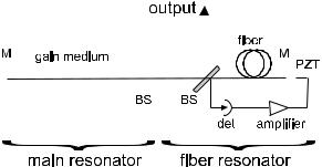
Figure 10.13: Schematic setup of a soliton laser, a.k.a. additive pulse mode locked (APM) laser. M: mirror, BS: beam splitter (partially reflecting mirror). Both resonators are arranged to be synchronous by careful length adjustment. The servo loop consisting of detector det, amplifier, and the piezoceramic transducer PZT maintains the length with interferometric stability.
unused port and measured by a photodetector. After electronic processing, it is fed to a piezoceramic transducer which serves to fine-tune the fiber resonator length. The processing involves subtraction of a manually set suitable reference value and amplification with what is known in control systems engineering as a PI (proportional-integral) characteristic (Fig. 10.13).
Later on it turned out that the concept is more general than to be restricted to the wavelength regime of anomalous dispersion in the fiber. The relevant mechanism is the Kerr nonlinearity which creates a self phase modulation. In the interference process this is translated to a modification of the pulse shape, usually a reduction of the duration. Dispersion is not really too important in this. This insight led to the concept of “additive pulse modelocking” (APM), also known as “interferential modelocking” or “coupled cavity modelocking”[109]. Several di erent types of lasers were used in this way to generate short pulses, including Nd:YAG lasers at both 1,064 and 1,319 nm.
10.2.5Pulse Interaction
It is the remarkable property of a soliton that it induces a perturbation of the refractive index in the fiber which is just right to make it hang together and keep its shape. If more than a single pulse propagates down the fiber, each of them can “feel” the perturbation of the refractive index caused by its neighbor, in particular when they get into close proximity with each other. The relevant question to ask is for the relative phase of the optical field of the two pulses in their slopes where they overlap: are the fields in phase, in opposite phase, at any other phase angle? For the “in phase” situation, there is constructive interference, and each pulse “feels” a stronger index modulation on that side that faces the other pulse. This perturbation acts asymmetrically on the pulse (Fig. 10.14)!
For opposite phase the fields interfere destructively, and the power in the overlap region is less than what it would be in the absence of the other pulse. Again, there is an asymmetric (one-sided) e ect.
204 |
Chapter 10. A Survey of Nonlinear Processes |
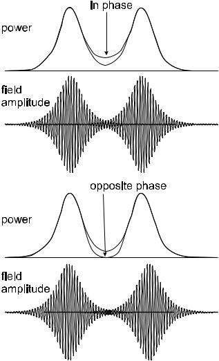
Figure 10.14: Interaction of co-propagating light pulses. Upper part : Two pulses are in phase with each other. Constructive interference will then increase the intensity in the middle, as compared to the case that the other pulse is absent. Lower part : Opposite phase pulses interfere destructively; the intensity profile goes down in the middle. Pulses are always attracted to the point of highest intensity (and thus, index). Then, in-phase pulses experience mutual attraction, opposite-phase pulses, repulsion.
In-phase pulses will both move slightly toward their mutual center-of-mass, opposite-phase pulses will move away from each other. This interaction force was first demonstrated in [106] after a theoretical prediction had been made in [53].
In e ect, there is what can be described as a force between the light pulses. Depending on the relative phase, this force can be attractive or repulsive. If
10.2. Anomalous Dispersion |
205 |
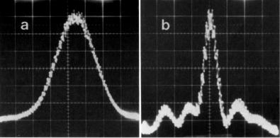
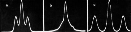
Figure 10.15: Experimental proof of pulse interaction forces. Autocorrelation traces of the pulse pair from the source (a) represents a double pulse, consisting of two humps each 0.9 ps wide and separated by 2.33 ps. (About the interpretation of autocorrelation traces see Appendix F.) If the pulses have the same phase, after traveling down 340 m of fiber they have moved toward each other so far that they are no longer resolved (b); for opposite phase, they have moved away from each other (c). From [106].
one lets the separation between the pulses slide to tune the relative phase, the force will basically change in a sinusoidal fashion. Once the separation increases noticeably, the force will be reduced exponentially because the slopes of sech pulses roll down exponentially. Once pulses are separated more than five or seven or so pulse widths, the interaction force becomes negligible.
The first experimental proof [106] is shown in Fig. 10.15. Time measurements on a femtosecond scale are only feasible by way of the autocorrelation technique (see Appendix F). In this experiment the interaction was easily measured. It was also found that in the case of attraction the pulses move toward each other, but they do not collide: this is surprising because collisions would be expected both intuitively and by the nonlinear Schr¨odinger equation. However, higherorder e ects perturb the pulses as they get increasingly close to each other so that eventually they actually fly apart [88].
The concept of attraction and repulsion can be extended to the case of chirped pulses where it is not so straightforward to speak of in-phase or oppositephase pulses, see [63].
10.2.6Self-Frequency Shift
One might be forgiven for adopting the following simple-minded approach to pulse propagation in optical fiber: While it is possible that the pulse shape is corrupted by influences like dispersion and self-phase modulation, the optical center frequency remains una ected. However, the exact opposite is true: Dispersion and self-phase modulation combine in such a way that in the case of solitons the pulse shape is preserved; the optical center frequency, however, is shifted. This latter fact was first discovered experimentally [105] and is easily explained by considering the e ect of Raman scattering [54].
The Raman gain spectrum is broad and, as Fig. 9.27 shows, begins at very small frequency detunings. Therefore, there is Raman self-pumping even within the bandwidth of a single pulse: The high-frequency slope acts as a pump for the low-frequency slope. As a result, the spectral center-of-mass of the pulse shifts continuously toward lower frequencies. If the pulse is a soliton, then its inherent robustness lets it hang together as an entity; pulses of inferior structural stability are likely to decay in the process (Figs. 10.16 and 10.17).
206 |
Chapter 10. A Survey of Nonlinear Processes |
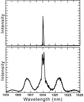
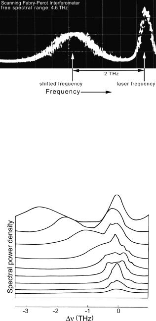
Figure 10.16: First observation of the soliton self-frequency shift. The figure shows the power spectrum at the far fiber end when short laser pulses are launched into the near end. The soliton is easily recognized due to its broad spectrum. With respect to the laser frequency (at which there is a narrower peak), the soliton is shifted downward in frequency. The amount of shift fluctuates with the laser power because the power defines the soliton width (this was explained in Sect. 9.4.3); power fluctuations during exposure of this photographic picture result in a “flat rooftop” of the soliton. From [105].
Figure 10.17: Soliton self-frequency shift as a function of launch power. Here power was varied over a wide range with a modulator; its control voltage also produced the o set between traces. It is clearly visible that the soliton’s spectral width increases with increasing power; so does the spectral shift. Only above a certain threshold does the soliton spectrum become visible as a separate structure. From [105].
10.2. Anomalous Dispersion |
207 |
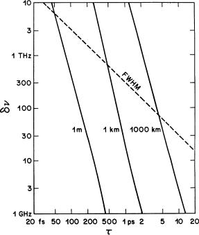
Figure 10.18: Expected amount of self-frequency shift. The shift basically scales with the inverse fourth power of pulse duration. From [54] with kind permission.
The amount of frequency shift depends strongly on the pulse duration: As the pulses get shorter, peak power grows quadratically, and the spectral width linearly. The Raman gain curve grows approximately linearly for small detunings (see Fig. 9.27). Taking all this together, the frequency shift is proportional to the inverse fourth power of pulse duration [54] (see Fig. 10.18). For 1 ps pulses the e ect is so weak as to be noticeable only after very long distances; for 10 ps it may be safely neglected in almost all cases. On the other hand, for subpicosecond pulses, the frequency shift becomes a dominant e ect: A pulse of less than 100 fs duration is shifted considerably after only 1 m propagation distance in standard fiber. The shift can reach large values, amounting to a noticeable fraction of the optical frequency. However, even a strong shift slows down to a halt once the pulse is shifted by hundreds of nanometers toward longer wavelengths because at the longer wavelength the fiber probably has much higher dispersion, and also is no longer a low-loss medium. These modifications conspire to reduce the peak power and increase the duration so that the frequency shifting rate comes down.
10.2.7Long-Haul Data Transmission with Solitons
Fundamental solitons are the natural units, or bits, for the transmission of information over optical fiber. They are more robust and stable than any other pulse because they embrace Kerr nonlinearity in the first place, and therefore