

Fiber_Optics_Physics_Technology
.pdf9.7. Inelastic Scattering Processes |
187 |
( )
 ( )
( )
Figure 9.25: The backscattered wave (the Stokes wave) has a deep and irregular temporal modulation, a result of the origin of the Stokes wave in spontaneous scattering processes.
Figure 9.26: The Fourier spectrum pertaining to the data shown in Fig. 9.25. The modulation of the Stokes wave extends up to tens of megahertz. This bandwidth is related to the damping rate of the acoustic wave in the nanosecond regime.
presence of optical feedback by reflection at the fiber ends, a resonator is formed; its round trip frequency (the inverse of its round trip time) constitutes a preferred frequency. If the reflections are strong enough, the modulation turns from irregular to periodic with nearly this frequency [39].
Without feedback, this modulation contains frequencies up to nearly 100 MHz. This limit is related to the damping rate of phonons, which is a few nanoseconds and which also sets the spectral width of the Stokes wave. Therefore, the Brillouin line width (SBS line width) is about νB ≈ 10 MHz, corresponding to a relative width of 10−3.
There is an important conclusion with regard to some fiber applications here. It is often the case that in laser-based materials processing the laser power must

188 |
Chapter 9. Basics of Nonlinearity |
be delivered from a bulky laser head to various positions on the workpiece. Fiber would provide perfect flexibility here, but SBS poses a severe limitation, and renders the idea to transmit sheer power useless unless extra measures are taken.
One such measure can be to avoid near-monochromatic pump light. For broadband pump light (band width νp), the e ective Brillouin gain is reduced according to
νB
g˜B = gB νB + νp .
For short pulses of light, the threshold is then higher because the pulse is spectrally wider than the SBS line width. The consequence is that for short, i.e., broadband, pulses, the threshold becomes much higher than the SRS threshold when the pulses have picosecond width. In that case SBS loses its importance.
We should also point out that the Brillouin gain mechanism, most often a nuisance, can in some cases actually be desirable. It can be exploited to build a Brillouin laser which can provide laser oscillation on a frequency o set from the pump by one Brillouin shift. Since the latter is within the reach of direct electronic detection, such lasers have uses in certain heterodyning applications. Moreover, there are Brillouin e ect-based sensors which can, e.g., exploit the temperature dependence of the Brillouin frequency to assess temperature. In combination with (long) pulses and an evaluation of the temporal structure, one can even have a position-resolved measurement. Fiber-optic sensors are treated in Chap. 12.
9.7.2Stimulated Raman Scattering
We have seen that the frequency shift in the case of Brillouin scattering is about 10 GHz. Stimulated Raman scattering (SRS) typically causes a frequency shift of 10 THz or a relative shift of 10−1. Therefore, for SRS, we cannot use the approximation ωp/ωs ≈ 1 as we did for SBS.
Other than that we can describe the power of the SRS Stokes wave as a function of position in the fiber in analogy to the above. We obtain
dIs |
= gIpIs − αsIs. |
(9.64) |
dz |
The gain factor g is about gR = 0.1 pm/W. The corresponding equation for the pump wave is
dIp |
= − |
ωp |
(9.65) |
|
|
|
gIpIs − αpIp. |
||
dz |
ωs |
|||
Again we convince ourselves that in the lossless case (αs = αp = 0), the photon number is preserved:
d |
Is + |
ωs |
Ip = 0. |
dz |
|
||
|
ωp |
||

9.7. Inelastic Scattering Processes |
189 |
In analogy to the treatment above we find the threshold from
dIp
dz Ip(z) dIs
dz
By integration, we conclude
L
Ip0e−αpz
0
=−αpIp,
=Ip0 e−αpz ,
=gIsIp0 e−αpz − αsIs
=Is gIp0 e−αpz − αs .
dz = Ip0 1 − e−αpL = Ip0Le
αp
with the e ective interaction length Le introduced in Sect. 9.1. Now we solve
Is(L) = Is0 exp (gRIp0Le − αsL) .
Similarly as above, threshold is reached when without saturation Is,max = Ip,min holds. The gain term is roughly the same for SBS and SRS and comes to gIp0Le ≈ 20. By reinserting the values given above for gR, gB, and Le ,max, one obtains a threshold power in a fiber with Ae = 50 μm2 for SRS of about 500 mW, many times the value for SBS. Raman scattering becomes the dominant scattering process only when quite short pulses are used so that the Brillouin threshold rises considerably. Pulse durations on the order of 10 ps or less are required for this.
The frequency dependence of the Raman gain was first measured in [147] (Fig. 9.27); later on researchers also considered how it consists of several contributions with di erent temporal response [148, 149].
m/W)
(10factor 13–
gainRaman
1
pump wavelength: 1μm
0.5
0
0 |
10 |
20 |
30 |
40 |
Frequency difference (THz)
Figure 9.27: The frequency dependence of Raman gain. The maximum of the Raman gain spectrum is reached at a detuning between pump and signal of about 13 THz, but even at smaller detunings there is an appreciable gain. After [147] with kind permission.
190 |
|
|
Chapter 9. Basics of Nonlinearity |
||
|
|
|
|
|
|
|
|
|
|
|
|
|
|
|
|
|
|
|
|
|
|
|
|
|
|
|
|
|
|
|
|
|
|
|
|
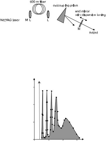
Figure 9.28: The first tunable Raman laser 1977 consisted of a fiber which was pumped by a modelocked Nd:YAG-Laser (1064 nm) with pulses of 200 ps duration. The average pump power was 1.1 W and the repetition rate 100 MHz. A prism served to separate pump and signal waves; a moveable end mirror provided tuning. The tuning range extended from 1,101 to 1,125 nm; an average power up to 20 mW was generated. The threshold was at 0.7 W pump power, and the slope e ciency was 60%. After [94] with kind permission.
Peak power (mW/1.5nm)
pump light 840 mW
150 |
S1 S2 S3 |
S4
100
S5
50
0
1.01.2 1.4 1.6
Wavelength (μm)
Figure 9.29: This Raman scattering spectrum was obtained by pumping a fiber with a Nd:YAG laser at 1,064 nm. The Stokes wave acts as a pump for the next order Stokes wave. This way five orders of Raman scattering are generated in this example. From [36] with kind permission.
Like SBS, SRS is suitable for use in amplifiers and lasers; these are then called fiber Raman amplifiers or lasers, respectively. Figure 9.28 shows an experiment in which a tunable Raman laser was built [94].
Raman amplification of a signal wave by the energy taken from a pump wave was shown in several experiments; a gain of, e.g., 30 dB was obtained. An important consideration for such amplifiers is the frequency di erence (detuning) between both waves as dictated by the Raman gain spectrum of fibers. The gain factor acquires its maximum near a detuning of 13 THz. Nd:YAG pump lasers emit either at 1.06 or at 1.32 μm; this is suitable for signal wavelengths of

9.7. Inelastic Scattering Processes |
|
|
|
|
|
|
|
|
191 |
||||||||||
|
|
|
|
|
|
|
|
|
Fiber |
|
|
|
|
|
|
|
|
|
|
Pump light |
|
|
|
|
|
Fiber - Bragg gratings |
Output |
||||||||||||
|
|
|
|
|
|
|
|
|
|
|
|
|
|
|
|
||||
|
|
|
|
|
|
|
|
|
|
|
|
|
|
|
|
|
|
|
|
1,117 |
|
1,480 |
1,395 |
1,315 |
1,240 |
1,175 |
1,117 |
1,175 |
1,240 |
1,315 |
1,395 |
1,480 |
1,480 |
|
|||||
|
|
|
|
|
|
|
|
Wavelengths (nm) |
|
|
|
|
|
|
|
|
|
|
|
Figure 9.30: A Raman laser using a cascade of several Raman orders for the generation of light with longer wavelength. Several selective reflectors (fiberBragg gratings) form nested cavities which support the pump wave, the targeted Stokes order, and all intermediate orders. The numbers shown in the example refer to the case described in [58] where fifth-order Raman scattering transfers power from a pump wave at 1,117 nm to a new wavelength of 1,480 nm. After [58].
1.12 or 1.40 μm, respectively – certainly not ideally suited wavelengths for the purposes of fiber optics.
If the Stokes wave has su cient intensity, it can itself act as pump wave for another scattering process; this way a second scattered wave can be generated, and even higher orders may be generated, too. Figure 9.29 shows a case in which no less than five Stokes orders appear [36]. In devices called Raman cascade lasers as shown in Fig. 9.30 this can be utilized in an arrangement of nested cavities for several Stokes orders to transfer power across larger frequency di erences (see, e.g., [41]).
When Raman gain is used to provide gain for a signal transmitted through the fiber, it should be clear that su cient pump power must be available and that the pump frequency must ideally be 13 THz above the signal frequency. Fortunately, the Raman process is not sharply resonant but fairly broadband so that there is some tolerance in the signal frequencies suitable for a given pump. Active fibers like Er-doped fibers described above (Sect. 8.8.1) have a much narrower gain band, fixed once and for all by properties of the Er ion. They are therefore not as universally applicable. As increasingly massive wavelength division multiplex transmission is employed to make use of an ever-increasing bandwidth (see Sect. 11.1.5), the Er gain band begins to be a limitation for state-of-the-art systems. Raman amplifiers therefore attract more attention again recently.
Chapter 10
A Survey of Nonlinear
Processes
10.1Normal Dispersion
10.1.1Spectral Broadening
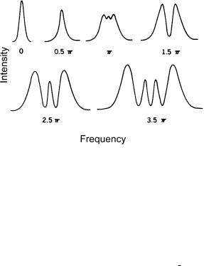
Self-phase modulation (SPM) broadens the frequency spectrum. This e ect is not pronounced as long as the peak nonlinear phase shift remains below π or so. At a few π, however, the spectrum begins to develop strong undulations as shown in Fig. 10.1.
Figure 10.1: Calculated spectral broadening by SPM; the maximum nonlinear phase shift is given as a parameter. From [146] with kind permission.
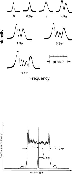
The figure is based on numerical calculations based on the nonlinear Schr¨odinger equation. This prediction is borne out well by experiment, as shown in Fig. 10.2. Intense light pulses in su ciently long fiber easily achieve φnl π. Then the spectrum takes a nearly rectangular shape (Fig. 10.3), mostly an e ect of the linear chirp across the central part of the pulse.
F. Mitschke, Fiber Optics, DOI 10.1007/978-3-642-03703-0 10, |
193 |
c Springer-Verlag Berlin Heidelberg 2009
194 |
Chapter 10. A Survey of Nonlinear Processes |
Figure 10.2: Observed spectral broadening by SPM; the maximum nonlinear phase shift is given as a parameter. From [146] with kind permission.
This spectral broadening may be desirable, e.g., to filter out di erent frequency components simultaneously. Sometimes, one wishes to generate a spectral continuum over a certain frequency range. Our main interest at this point, however, is that a broad spectrum is an important prerequisite for the
Figure 10.3: Spectral broadening by self-phase modulation can, in extreme cases, give a nearly rectangular spectrum. Here the pulses were taken from a frequency-doubled Nd:YAG laser (532 nm) and had a duration of 35 ps. After [77] with kind permission.
10.1. Normal Dispersion |
195 |
generation of shorter pulses. In other words, strong self-phase modulation is a step toward pulse compression.
10.1.2Pulse Compression
Let us assume that a light pulse has assumed a broad spectrum by self-phase modulation. Then, there will be a strong chirp in its temporal evolution.
Now, if all this happens in the presence of normal dispersion, the di erent spectral components of the pulse will be stretched out temporally. Then, the pulse will take on a nearly rectangular temporal profile with a very nearly linear chirp when the components responsible for the flat central part of the spectrum are rearranged in time.
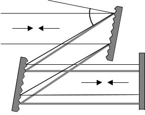
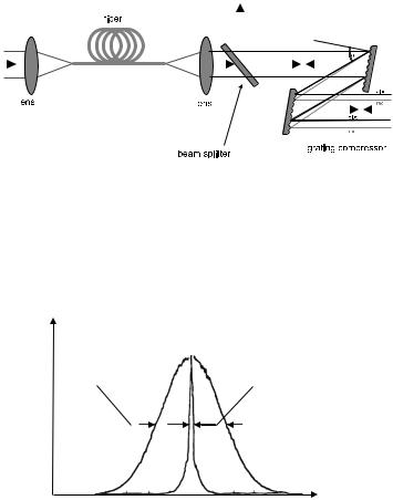
By using a di raction grating, one can generate an opposite (anomalous) dispersion which can recompress the distorted pulse to the shortest duration compatible with its spectral width. A pair of gratings (see Fig. 10.4) is more convenient to handle. A combination of a fiber and a grating pair as sketched in Fig. 10.5 is available commercially as a pulse compressor. It works in the wavelength regime where the fiber is normally dispersive (which is useful for light from dye lasers or Nd:YAG lasers), and it can considerably reduce the pulse duration, as shown in Figs. 10.6 and 10.7.
θ
blue
red
blue
red
Figure 10.4: Schematic representation of dispersion from a pair of di raction gratings. Shorter wave light (labelled as ‘blue’) takes a shorter path than longer wavelength light (‘red ’).
10.1.3Chirped Amplification
There are now laser systems capable of generating peak powers of more than 1 PW. They rely on an oscillator–amplifier concept: Pulses generated by an oscillator are amplified and brought well into the terawatt regime and above. Such light sources are important tools for basic physics research.
The technical di culty is that optical components of the amplifier must withstand the enormous intensities and thus are subject to a damage hazard.
196 |
|
|
Chapter 10. A Survey of Nonlinear Processes |
|||||||||||||||
|
|
|
|
|
|
|
|
|
|
|
|
|
|
|
|
|
|
|
|
|
|
|
|
|
|
|
|
|
|
|
|
|
|
|
|
|
|
|
|
|
|
|
|
|
|
|
|
|
|
|
|
|
|
|
|
|
|
|
|
|
|
|
|
|
|
|
|
|
|
|
|
|
|
|
|
|
|
|
|
|
|
|
|
|
|
|
|
|
|
|
|
|
|
|
|
|
|
|
|
|
|
|
|
|
|
|
|
|
|
|
|
|
|
|
|
|
|
|
|
|
|
|
|
|
|
|
|
|
|
|
|
|
|
|
|
|
|
|
|
|
|
|
|
|
|
|
|
|
|
|
|
|
|
|
|
|
|
|
|
|
|
|
|
|
|
|
|
|
|
|
|
|
|
|
|
|
|
|
|
|
|
|
|
|
|
|
|
|
|
|
|
|
|
|
|
|
|
|
|
|
|
|
|
|
|
|
|
|
Figure 10.5: Pulse compression with fiber and grating pair. The fiber generates strongly chirped pulses due to self-phase modulation. With a grating arrangement of judiciously chosen dispersion the chirp is compensated, and the pulse duration is reduced in the process. The figure shows a setup with double pass through a grating pair and output coupling from a beam splitter (partially reflecting mirror).
Autocorrelator signal
|
|
|
|
|
|
after compression, |
before compression |
|
shown on a |
||||
|
5x expanded scale |
|||||
33 ps |
|
410 fs |
||||
|
|
|
|
|
|
|
–40 |
–20 |
0 |
20 |
40 |
Time (ps)
Figure 10.6: Experimental result with fiber-grating compressor: Here pulses of initial width 33 ps were compressed down to 410 fs. From [76] with kind permission.
This can be avoided by the concept of “chirped pulse amplification” or CPA [126], which has its origin in radar technology and is a method to avoid high peak powers acting on components. One inserts a dispersive element – either a fiber or a grating – after the oscillator to produce a strong dispersive broadening of the pulse, with the accompanying reduction in peak power. The spectral components of the pulse then do not occur at the same time but sequentially. This predistorted pulse is fed to the amplifier where the highest intensity peaks are now reduced by the broadening factor. This can amount to several orders of magnitude, and the damage risk is drastically reduced. After amplification, all Fourier components are shifted together again by sending the pulses through another dispersive element which has the same absolute value of dispersion, but
10.1. Normal Dispersion |
197 |
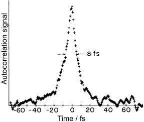
Figure 10.7: Extreme pulse compression down to 8 fs. For some time in the 1980s, this result represented the world’s shortest pulses. From [87] with kind permission.
the opposite sign. An example is shown in Fig. 10.8 where the first dispersive element is a fiber, the second, a grating.
CPA is now the method of choice to produce petawatt powers in several laboratories around the world. To put this into perspective, consider that all electric power generated in the USA is below 1 TW. Of course, the petawatt level is maintained only for a split second, indeed, a few hundred femtoseconds. A pioneering experiment at the Lawrence Livermore Laboratory 1999 [126] demonstrated pulses with peak power ≥ 1 PW, 680 J energy, and a duration of 440 fs. Pulses were stretched 25,000-fold before amplification. Recompression had to be performed in vacuum due to the enormous field strength of the final pulse. It exceeded by three orders of magnitude those typical field strengths by which electrons are bound to nuclei in most atoms; any material would instantly break down. When focused, an intensity of 1025 W/m2 was obtained at an energy density of 30 PJ/m2; this is a lot more than inside stars.
In this case, however, fibers were not used but rather a combination of gratings. While it is true that fibers provide more dispersion, there are also contributions from higher-order dispersion that make it di cult to undo the chirp completely. Also, on a grating one can distribute the power over a larger area, thus reducing intensity and risk of damage. Therefore, fibers are preferentially found in systems that do not aim at the ultimate power limit but that are intended to work as a handy laboratory tool. Commercial CPA systems are available.
10.1.4Optical Wave Breaking
We have seen above that through strong self-phase modulation, pulses acquire an almost rectangular spectrum. In the presence of normal dispersion, the spectral components are pulled apart temporally, so that there is an almost linear chirp