

Fiber_Optics_Physics_Technology
.pdf5.4. Ultimate Reach |
83 |
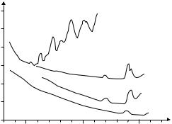
2.55.0 7.5 10.0
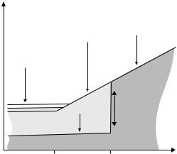
Figure 5.6: Typical spectral transmission curves of some infrared fibers.
over short distance in comparison. All-important is a high damage threshold. Obviously, in a hollow core, the refractive index is close to 1. Light-guiding takes place only because, in wavelength regimes of strongly anomalous dispersion, the index of the cladding may actually fall below 1. In some doped silica glasses and in sapphire, this occurs around the wavelength of the CO2 laser.
Hollow core fibers are also used in reverse: We will discuss fiber-optic sensors in Chap. 12 but here we jump ahead and mention that the peak wavelength of black body radiation around room temperature is within the transmission range of these fibers. Therefore, the temperature of objects can be measured by gathering radiation with a hollow core fiber without even touching the object, and guide it to a measuring device. This is an admittedly expensive, but sometimes very useful clinical thermometer!
5.4.3Sapphire Fibers
Sapphire is a chemically stable, nontoxic material with reasonable mechanical strength. It can be worked into fibers by growing from a solution of Al2O3. Sapphire fibers transmit from the visible range to about 3 μm. Bend radii are limited to a few centimeter, and loss is around 1 dB/m. Sapphire fibers, too, are fabricated without cladding and with 100–500 μm diameter. They have good damage threshold and high melting point, which makes them attractive for transmission of high-power laser light, including laser delivery in surgery and dentistry.
Like hollow core fibers mentioned in the previous paragraph, sapphire fibers can be used as a part of an infrared thermometer. Their good heat resistance and chemical stability are favorable for applications in chemically harsh and/or high-temperature environments, like inside chemical reactors where sapphire fibers may o er the best way to measure temperature.
5.4.4Plastic Fibers
Also suitable only for short-distance transmission are plastic fibers, usually called POF (plastic, or polymeric, optical fiber) for short. However, they are used in an entirely di erent field of application. Plastic is a low-cost material and can be shaped very easily into fibers (or any other shape). In most widespread use is polymethyl methacrylate (PMMA), a.k.a. acrylic glass, perspex, or plexiglas; PMMA was used for the first commercially available POF as early as 1963. Polycarbonate and polystyrene are other options.
84 |
Chapter 5. Losses |
100,000
(dB/km) |
10,000 |
|
|
||
Attenuation |
1,000 |
|
100 |
||
|
||
|
10 |
|
|
1 |
|
|
0,1 |
PMMA
PF-PMMA
PF-PMMA, theoretical limit
fused silica
500 |
1,000 |
1,500 |
Wavelength (nm)
Figure 5.7: Typical spectral transmission curves of polymethyl methacrylate (PMMA) light-guiding fibers. Data are taken from gradient index fibers. “PF” refers to perfluorinated material. After [32] with kind permission.
In comparison to fused silica, the optical loss in POFs is enormous and is measured in dB/m rather than dB/km (see Fig. 5.7). While Rayleigh scattering and absorption from electronic transitions and from contaminants also exist in POFs, the dominant loss mechanism seems to be the absorption at harmonics of the CH bond, which is ubiquitous in plastic materials [81]. A successful approach to reducing this problem is to replace some of the hydrogen with heavier molecules such as fluorine, to shift the resonance. However, fluorination is an expensive process, so that the low-cost advantage is somewhat reduced.
Nevertheless, in terms of low loss, POFs cannot match silica-based fiber. Their maximum transmission distance is therefore defined by loss, not by dispersion. It is thus not a problem that realistically only multimode fibers with large numerical aperture can be made. Core diameters are often 1 mm or even more. A cladding can be made from fluorinated PMMA if internal guiding is desired. A typical numerical aperture can be 0.3.
Certainly, POFs have several quite favorable aspects: Handling is easier than for fused silica, incoupling e ciency is good, and coupling between fibers is quite simple. All this adds to the low-cost aspect. One drawback is that these fibers can be damaged by high-power lasers. Thus the applications are outlined: Plastic fibers are useful for short-distance data transmission where cost limitations are stringent. Local area computer networks within a building or on premises are an example. Also, in some stereo equipment, there is optical transmission between digital audio components such as CD players, DVD recorders, etc. European car makers have been using POFs for some time because interesting savings of weight are obtained (a series 7 BMW car contains more than 100 m POF). There are also plans to use an on-board POF network to provide the car driver and all passengers individual access to a range of entertainment media. Quite naturally, the aviation industry is also increasingly using POF.
Part III
Technical Conditions for Fiber Technology
A variable “wave plate” in all-fiber technology used to adjust the state of polarization. It consists of three rotatable fiber loops and permits to translate any given state of polarization into any desired state. These components are described in Sect. 8.5.1.

Chapter 6
Manufacturing
and Mechanical Properties
6.1Glass as a Material
Blood is a quite peculiar juice. Thus spoke Mephistopheles in the tragedy “Faust” by J. W. v. Goethe. Glass, too, is a quite peculiar juice: There was a stone age, an iron age, and a bronze age. Glass, however, is the only artificial material that has been in use uninterruptedly for seven millennia or more without giving its name to an epoch.
Like the word “crystal,” “glass” refers not to a chemical but to a physical property. Unlike a crystal, its structure is not neatly ordered but quite irregular. Glass is a liquid usually mistaken for a solid! But let us start at the beginning.
6.1.1Historical Issues
The oldest finds date back about 7,000 years before Christ, at the end of the younger stone age. They hail from the Mideast: Egypt and Mesopotamia, present-day Iraq. Independently the art of making glass was also developed in Mykenae (Greece), China, and North Tyrol.
Making glass is closely related to pottery, which has existed in Egypt more than 8,000 years ago. Maybe by chance people had discovered that a glazing develops when sand with lime content is exposed to fierce heat together with soda ash. Beginning about 1,500 BCE, glass was made without ceramic substrate. Blowing glass dates back to ca. 200 BCE in Sidon and Babylon. In the Roman Empire, glass articles were coveted luxury objects.
In the middle ages, Venice was an important center of the art of glass blowing. Up to 8,000 people worked there. Further north in Central Europe, glass was mainly made in remote forested areas such as the German Spessart, the Thuringian and Bavarian Forests, and the Erzgebirge (“ore mountains” on the German–Czech border) because there both potash and fire wood were in abundant supply. (Potash, or potassium carbonate K2CO3, is the main constituent of wood ashes: All plants contain potassium salts.) Until the seventeenth century, in part the eighteenth century, there were traveling glass makers. To our day
F. Mitschke, Fiber Optics, DOI 10.1007/978-3-642-03703-0 6, |
87 |
c Springer-Verlag Berlin Heidelberg 2009
88 |
Chapter 6. Fibers of Glass |
the glass industry in Central Europe is still concentrated to a good part near major forests such as the Bavarian Forest.
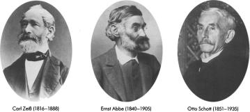
Modern glass technology was basically started by two Germans, Otto Schott (1851–1935) and Ernst Abbe (1840–1905) (Fig. 6.1). Schott, son of a glass maker’s family from Lothringia, conducted systematic experiments with almost all chemical element to determine which influence their addition to the melt would have on the properties of the final glass.
Figure 6.1: Carl Zeiss, Ernst Abbe, and Otto Schott are the founders of modern optics in which scientific methods and industrial processing are closely interwoven. From [170] with kind permission.
Abbe was a professor at the German university of Jena, and he was a coowner of the Carl Zeiss company. Zeiss needed high-quality glass in order to build optical instruments.
After many tries, Schott finally found the suitable glass recipe; this prompted a cooperation that then led to the start of “Jenaer Glaswerk Schott und Genossen” (Jena Glass Works Schott and Co.), which acquired some fame. For many specialized purposes, they developed just the right glass. The company did well, and we remark in passing that such fairly revolutionary social novelties as an 8-h work day and participation of employees in the company’s profits were introduced.
After the second World War, Americans moved specialists from Jena into what was to become Western Germany. This gave rise to the new location of Schott Glass Works in Mainz.
6.1.2Structure
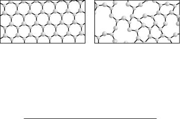
As mentioned above, both words “glass” and “crystal” do not refer to a specific chemical composition but to a particular spatial arrangement of molecules. In a crystal, molecules are arranged in a repetitive, periodic pattern. In glass, by comparison, they are arranged in a disorderly fashion: glass is amorphous. Correspondingly, in glass the molecules are not densely packed (Fig. 6.2). Many substances have glassy states; the table gives a few examples:
6.1. Glass as a Material |
89 |
Figure 6.2: Comparison of crystalline and glassy structures for the example of silicon dioxide. Symbolically shown are silicon ions (Si4−, small spheres), oxygen ions (O2−, larger spheres), and their electronic bonds. Due to the twodimensional nature of the sketch, silicon’s tetrahedron configurations with four bonds are depicted with three, rather than four bonds; the missing fourth bond may be imagined out of plane. In the crystal, there is high packing density; in glass, irregularities lead to lesser density.
Substance |
Glass temperature (K) |
Natural rubber |
200 |
PVC |
347 |
Water |
140 |
Glucose |
305 |
Selenium |
303 |
Beryllium fluoride |
570 |
Germanium dioxide |
800 |
Silicon dioxide |
1,350 |
|
|
Only a limited selection of glassy substances is useful in the optics industry. We will deal almost exclusively with glass of silicon dioxide. Silicon, after oxygen, is the second most frequent element in the earth’s crust (28%). It is found in the form of silicates, silicic acids, and as anhydride SiO2 (and of course, these days, in elementary form inside of computers). Silicic acid is a name for the oxygenic acids of Si, that is, SiO2(n · H2O) where the case of n = 0 (SiO2 in its various forms) is sometimes included. In particular, ortho silicic acid H4SiO4 occurs frequently. Over geological time spans, it may shed water and go through intermediate stages like H2Si2O5 until finally it becomes the anhydride SiO2.
The most important crystalline form of SiO2 is quartz. It constitutes the most important part of silicate rocks; there are also feldspar (KAlSi3O8), mica (KAl2[AlSi3O10](OH)2), and salts of polysilicic acids containing Mg++ and Ca++. Among these quartz is the hardest. During geological time scales, quartz is ground down and destroyed, and small fragments remain: gravel or sand. Traces of soluble silicic acid in the waters of rivers and the sea are incorporated by plants and animals for mechanical hardness.
Depending on its crystalline modification, quartz has a melting point of 1500–1700◦C and a density of 2.3–2.6 g/cm3. Geologically it is found in transparent crystals up to a meter in size. In form of smaller crystals, quartz is contained in all primary rocks such as granite, porphyry, and gneiss. Amorphous SiO2, often colored by other substances, is the basis of semiprecious stones such as agate, chalcedony, and opal.
90 Chapter 6. Fibers of Glass
Glass is obtained for melting together quartz sand, soda ash, potash, and metallic oxides. Soda ash means sodium carbonate (Na2CO3) and potash is potassium carbonate (K2CO3). If one uses colorless metallic oxide such as CaO and white (iron-free) quartz sand, one obtains clear glass; addition of other elements can change the properties. Green or brown bottle glass is made from ordinary yellow sand (containing iron); other additives are common to control the color. Window glass consists of Na2O CaO 6 SiO2. Lead glass, used extensively in optics for its high refractive index, consists of K2O PbO 6 SiO2. Laboratory glass is similar to window glass, except that there are additions of 8% Al2O3, 5% B2O3, and 4% BaO. If a lot of Al2O3 is mixed in, SiO2 and Al2O3 will no longer mix and the substance turns turbid in the oven, stays white, and is not transparent. This is called porcelain, or china.
The main characteristic of glass, its structural irregularity, is reflected in its heat conductivity, which is about one order of magnitude lower than for the corresponding crystal. With this structure, glass is in a local, but not a global minimum of free energy (Fig. 6.3). Consequently a deglassing, a growing of crystalline structure, may occur – albeit on very long time scales due to the enormous viscosity of glass. Over historic time spans, glass can be a ected to a measurable amount: very old glass turns turbid and brittle.
Volume |
liquid |
supercooled liquid |
glass |
(value depends on cooling rate) |
melting |
crystal |
crystallizing |
Temperature |
Glass temperature Melting temperature
Figure 6.3: Glass is a sti ened undercooled liquid. Starting from a crystal, by raising the temperature it will melt. When the temperature is lowered again, there can be undercooled melt rather than recrystallization. This melt then sti ens and becomes glass. In comparison, glass is less densely packed than crystal, thus occupies a larger volume. In principle, glass can recrystallize over long periods of time.
Why would one use glassy, not crystalline material for light-guiding fibers? Crystals can never be made entirely without defects and dislocations, but these act as e cient scatterers of light so that losses are higher. Moreover, crystals tend to be brittle so that glass comes out as the better choice. The reader is referred to [57] for more detail about defects in silica glass.
6.1. Glass as a Material |
91 |
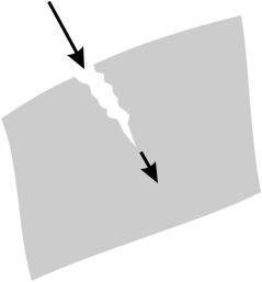
6.1.3How Glass Breaks
When it comes to glass, the layperson does not necessarily think of great elasticity. Rather, the common perception is that glass breaks quite easily. This may be why it is so fascinating to experience the perfect flexibility of optical fibers. It is true, though, that cracks can occur in glass, which suddenly, precipitously cause it to break (Fig. 6.4). On closer inspection, what happens is that fractures propagate across the material at a speed of hundreds of meters per second (approaching half the velocity of sound). But that is not true for all cracks: Quite to the contrary, many tiny cracks advance only at an unperceptibly slow speed, often at 10−12 m/h, which corresponds to one snapping atomic bond per hour. Then visible damage will arrive only after years, after a false sense of safety has developed.
If pristine glass pieces are tested under high vacuum, they withstand tensions of more than 10 GPa, about ten times the value for many metal alloys. Surface defects or contact with abrasives produces microscopic cracks, though, which are the point of attack for chemicals. The cracks then grow and widen. The gravest concern is about water because it is so ubiquitous. It acts at the tip of the crack. As is well known, window panes are cut to size not with a saw as one would do with wood, but by making a scratch with a diamond, wet it with water or even saliva, and then break it. This is the same mechanism.
Atoms at the glass surface have fewer bonds than those inside the volume. Therefore they are at an elevated energetic state. Making the surface larger then requires an energy supply. When the mechanical energy stored in the material is larger than this additional surface energy, the crack will grow. Chemical reactions between the silica and intruding water reduce the required energy from 3.2 to 0.19 eV per bond.
A lot of mechanical stress builds up, at the tip of the crack in particular. In cracks that are often about 0.4 nm, water molecules of 0.26 nm diameter
water etc.
glass
crack growth
Figure 6.4: Glass breaks from cracks that grow at their tip.
92 |
Chapter 6. Fibers of Glass |
and similarly sized ammonia molecules can intrude, but methanol (molecular diameter 0.36 nm) has a lot less consequence. Even larger molecules do not a ect crack growth appreciably.
It took a number of years until industry had learned to master the making of glass with the chemical purity required for fibers. Experience from semiconductor industry was a valuable guide in the process. In that industry, gaseous silicon chloride (SiCl4), purified by distillation, is widely used as a starting material. It is now also being used for making glass, according to the reaction formula
SiCl4 + O2 → SiO2 + 2 Cl2. |
(6.1) |
Gaseous chlorine evaporates; solid silicon dioxide condenses as an amorphous substance on cool surfaces and can form glass at suitable temperatures (“fused silica”).
Especially critical for purity are OH ions. The following reaction, for example, must be avoided:
2 SiCl3H + 3 O2 → 2 SiO2 + 3 Cl2 + 2 OH. |
(6.2) |
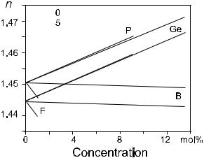
Dopants serve to modify the refractive index (Fig. 6.5). Germanium and phosphorus both increase; fluorine decreases the index. The most frequently used dopant is germanium. Dopants are added through their chlorides to the reaction gas, and there can be the following reaction:
GeCl4 + O2 → GeO2 + 2 Cl2. |
(6.3) |
As a rule of thumb, a concentration of 1 mol% GeO2 in fused silica raises the index by 0.1%.

 ,
, 


 ,
, 

Figure 6.5: Influence of dopants on the refractive index at 1.0 and 1.5 μm. Shown are data for phosphorus (P2O5), germanium (GeO2), boron (B2O5), and fluorine. Calculated after [171].
6.2. Manufacturing of Fibers |
93 |
6.2Manufacturing of Fibers
The manufacturing of optical fiber is performed in two steps: First a preform is made. The term refers to a rod of glass, typically ca. 1 m long, with a diameter of 10–50 mm, and with the refractive index profile already built into it. In the second step, this preform is then softened by heating and stretched out by pulling so that the final fiber is obtained.
Both process steps will now be described in some more detail. For making of the preform there are several alternative ways. All of them have certain advantages and disadvantages; each manufacturer tends to advertise the advantages, indeed the superiority of their particular proprietary technique.
6.2.1Making a Preform
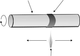
OVD
Outside vapor deposition, a technique also known as soot process, was the first process to achieve the reduction of losses to 20 dB/km in 1973 (Fig. 6.6). It was developed by Corning Glass Works; it is still used at Corning and, through joint ventures, at other manufacturers.
Glass is deposited on the outside of a massive cylindrical rod of aluminum oxide. It is generated when the gaseous chemicals are fed into the flame of a burner so that submicroscopic glass particles condense on the surface. All the time the rod is rotated and translated so that a uniform layer is formed. The layer is porous at first (“soot”), but during its deposition concentrations of dopants are adjusted, and it therefore already contains the dopant profile as required for the refractive index profile of the finished fiber.
Then this rig is heated to allow evaporation of trapped gases and humidity. Next, heat is turned up to a higher temperature of 1400–1500◦C so that in a
carrier tube
deposition of SiO2
rotation
burner flame
translation
supply of SiCl4,
GeCl4, O2, etc. to burner
Figure 6.6: In outside vapor deposition (OVD), the glass is deposited from the reaction of gaseous chemicals on the outside surface of a carrier rod.