

mls94-complete[1]
.pdfordinate frame A shown in Figure 2.13. The wrench F written in A’s coordinate frame is given by
Fa = AdT Fb.
gba
This wrench represents the equivalent force/moment pair applied as if the coordinate frame A were rigidly attached to the object. This is not the same as simply rewriting the components of Fb in A’s coordinates, since the point of application for Fa is the origin of the A frame and not the origin of the B frame.
If several wrenches are all applied to a single rigid body, then the net wrench acting on the rigid body can be constructed by adding the wrench vectors. In order for this addition to make sense, all of the wrenches must be represented with respect to the same frame. Thus, given a set of wrenches Fi, each wrench is first written as an equivalent wrench relative to a single coordinate frame and then the equivalent wrenches are added to determine the net wrench acting on the rigid body. This helps explain why equivalent wrenches include a shift of origin: one can only add wrenches if they represent forces and torques applied at a single point (such as the center of mass or a fixed spatial frame).
A net wrench F acting on a rigid body with configuration gab SE(3) has two natural representations. The body representation of the wrench is written as Fb and represents the equivalent force and moment applied at the origin of the B frame (and written in B’s coordinates). The spatial representation of the wrench is the equivalent wrench written in A’s coordinate frame. These representations are analogous to the spatial and body representations of the velocity of a rigid body.
As with velocities, it will be convenient to define the spatial and body representations of a wrench without explicit reference to a given set of
frames. If g |
|
SE(3) is the configuration of a rigid body, then |
||||
coordinate b |
|
|
s |
for the spatial wrench. These |
||
we write F |
for the body wrench and F |
|
||||
wrenches are related by the transpose of the adjoint matrix: |
|
|||||
|
|
|
F b = AdgT F s. |
(2.67) |
||
This notation mirrors that used for body and spatial velocities of a rigid body allowing the instantaneous work performed by a wrench F moving through a rigid motion with instantaneous velocity V to be written as
δW = V b · F b = V s · F s.
We leave the proof of this statement as an exercise.
Example 2.7. Preview of multifingered grasping
Consider the multifingered grasp shown in Figure 2.14. Let Fci be the wrench exerted by the ith finger on the grasped object, represented in
63

C1 |
O C2 

S1 |
P |
S2 |
Figure 2.14: Coordinate frames for a simple grasping example.
the frame Ci. The net wrench on the body, in the body coordinate frame O, is given by
X
Fo = AdT−1 Fc .
goci i
This is the basic calculation which is used in grasping to determine the net e ect of forces applied at the contact points between the fingers and the object.
5.2Screw coordinates for a wrench
As with twists, it is possible to generate a wrench by applying a force along an axis in space and simultaneously applying a torque about the same axis. The dual of Chasles’ theorem, which showed that every twist could be generated by a screw, is called Poinsot’s theorem. It asserts that every wrench is equivalent to a force and torque applied along the same axis. We begin by defining the notion of a wrench acting along a screw.
With respect to some fixed spatial coordinate frame A, let S be a screw with axis l = {q + λω : λ R}, kωk = 1, pitch h, and magnitude M . We construct a wrench from this screw by applying a force of magnitude M along the directed line l and a torque of magnitude hM about the line. If h = ∞, we generate a wrench by applying a pure torque about l. The resulting wrench, in A’s coordinates, is given by
|
ω |
|
|
F = M −ω × q + hω |
h finite |
(2.68) |
|
F = M |
ω |
h = ∞, |
|
|
0 |
|
|
|
64 |
|
|

where the term −ω × q accounts for the o set between the axis of the screw and the origin of A. We call F the wrench along the screw S. Note that F (and q and ω) are all specified with respect to the fixed coordinate frame A and hence F represents the spatial wrench applied to the rigid body. (We omit the use of subscripts in this section since all quantities are specified with respect to a single coordinate frame.)
To find the screw coordinates for a wrench, we solve equation (2.68) for ω, q, h, and M given F = (f, τ ). This leads to the following theorem:
Theorem 2.17 (Poinsot). Every collection of wrenches applied to a rigid body is equivalent to a force applied along a fixed axis plus a torque about the same axis.
Proof. The proof is constructive. Let F = (f, τ ) be the net wrench applied to the object. We ignore the trivial case, F = 0.
Case 1: (f = 0, pure torque). Set M = kτ k, ω = τ /M , and h = ∞. Equation (2.68) verifies that these are the appropriate screw coordinates.
Case 2: (f 6= 0). Set M = kf k, and ω = f /M . It remains to solve
M (q × ω + hω) = τ |
|||||
for q and h. One solution is given by |
|
|
|
||
h = |
f T τ |
|
q = |
f × τ |
. |
kf k2 |
|
||||
|
|
kf k2 |
|||
This solution is not unique since any q′ = q + λω will also satisfy equation (2.68). 
Using Poinsot’s theorem, we can define the screw coordinates of a
wrench, F = (f, τ ): |
|
|
|
1. Pitch: |
f T τ |
|
|
h = |
(2.69) |
||
kf k2 |
The pitch of a wrench is the ratio of angular torque to linear force. If f = 0, we say that F has infinite pitch.
2. Axis: |
( |
|
0 + λτ : λ R , |
if f = 0 |
|
||
|
l = |
{ |
kff×kτ2 |
+ λf : λ R}, |
if f 6= 0 |
(2.70) |
|
|
|
{ |
|
|
} |
|
|
The axis l is a directed line through a point. For f 6= 0, the axis
is a line in the f direction going through the point q = f ×τ . For
kf k2
f = 0, the axis is a line in the τ direction going through the origin.
65
3. Magnitude: |
( |
|
|
|
|
|
|
M = |
kf k, |
if f 6= 0 |
(2.71) |
|
kτ k, |
if f = 0 |
|
The magnitude of a screw is the net linear force, if the motion contains a linear component, or the net torque, otherwise.
The dual nature of twists and wrenches is evident in the screw coordinates for twists and wrenches. For example, a zero pitch twist corresponds to pure rotation, while a zero pitch wrench corresponds to a pure force (no angular component).
5.3Reciprocal screws
The dot product between twists and wrenches gives the instantaneous power associated with moving a rigid body through an applied force. As in the previous subsection, we carry out all calculations relative to a single coordinate frame and omit the use of subscripts. A wrench F is said to be reciprocal to a twist V if the instantaneous power is zero: F · V = 0. Since both twists and wrenches can be represented by screws, we can use this to define the notion of reciprocal screws:
Definition 2.3. Reciprocal screws
Two screws S1 and S2 are reciprocal if the twist V about S1 and the wrench F along S2 are reciprocal.
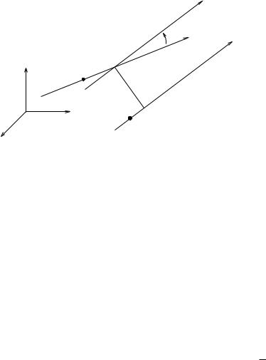
Classically, reciprocal screws are defined by using the reciprocal product between screws. Let Si be a screw with axis li = {qi + λωi : λ R}, pitch hi, and magnitude Mi. Given two screws S1 and S2, we define the distance d between the screws as the minimum distance between l1 and l2; this distance will be achieved along a line perpendicular to both l1 and l2. We denote this line as dn where n is a unit vector and d > 0. The angle α between S1 and S2 is the angle between the vectors ω1 and
ω2,
α = atan2(ω1 × ω2 · n, ω1 · ω2)
(see Figure 2.15). The reciprocal product between two screws is defined
as
S1 S2 = M1M2 (h1 + h2) cos α − d sin α . (2.72)
Proposition 2.18. Characterization of reciprocal screws
Two screws S1 and S2 are reciprocal if and only if
S1 S2 = 0.
Proof. We consider only the case where h1 and h2 are finite. The other cases are left as exercises. Let V be the twist about the screw S1 and F
66
|
α |
|
ω1 |
|
ω2 |
|
q1 |
S1 |
d |
q2
S2
Figure 2.15: Notation for reciprocal screws.
be the wrench along the screw S2:
V = M1 |
|
1 × |
ω1 |
|
|
F = M2 q2 |
× ω2 + h2ω2 . |
|
q |
|
ω1 + h1 |
ω1 |
|
|
ω2 |
Without loss of generality we can assume that q1 and q2 are the points at which the axes are closest and hence q2 can be rewritten as q2 = q1 + dn where n is the unit normal vector connecting the two axes. The instantaneous work between V and F is
V · F = M1M2 ω2 · (q1 × ω1 + h1ω1) + ω1 · (q2 × ω2 + h2ω2)
=M1M2 ω2 · q1 ×ω1 + h1ω1 · ω2 + ω1 · (q1 + dn)×ω2 + h2ω1 · ω2
=M1M2 (h1 + h2) cos α − d sin α ,
which is precisely the reciprocal product. Hence, by definition, the screws are reciprocal if and only if the reciprocal product is zero. 

If we represent screws using twist coordinates, then we can define the reciprocal product directly in terms of the components of the twists. Let V1, V2 R6 be two arbitrary twists. Then we define the reciprocal product between V1 and V2 as
V1 V2 = v1T ω2 + v2T ω1.
A similar relationship holds if we associate screws with wrenches. Reciprocal screws play an important role in analyzing the kinematic
properties of mechanisms. For example, in a grasping context we can view the wrenches applied to an object as a set of constraining screws and ask if there are any instantaneous rigid motions (twists) that do not violate the constraints. Such twists, if they exist, correspond to motions
67

F3
F2
F1
Figure 2.16: A set of pure forces acting on a rigid body.
of the grasped object which cannot be restricted by the fingers. This specific situation is considered in detail in Chapter 5, but we can give some preliminary indications of how the analysis might proceed using the concept of a system of screws.
As a motivating example, consider the grasping situation depicted in Figure 2.16. Suppose we constrain the motion of a rigid body by applying normal forces at several points around the rigid body. We would like to ascertain if there are any motions of the rigid body which cannot be resisted by these forces. Let {S1, . . . , Sk} represent the screws corresponding to the wrenches. Suppose that there exists another screw Sf such that Sf Si = 0. Then, interpreting Sf as a twist and each Si as a wrench, we see that motion along Sf causes no work to be performed against any of the wrenches. Hence, the wrenches cannot resist this type of motion and the object is free to move (instantaneously) along Sf .
If we interpret a set of screws {S1, . . . , Sk} as twists, then the twists form a linear space over the reals and hence we can talk about scaling and adding screws by interpreting this in terms of regular addition and multiplication on twists. We call the set of screws {S1, . . . , Sk } a system of screws and we define addition and scaling of screws by associating each screw with a unique twist.
It follows immediately from the definition of the reciprocal product that if S is reciprocal to S1 and S2, then it is reciprocal to any linear combination of S1 and S2 (with the linear combination performed in twist coordinates). Using this linearity property, we can define the set of all screws which are reciprocal to a given system of screws as the recipro-
68
cal screw system. A reciprocal screw system defines a linear subspace of twists. If we interpret a screw system as a set of wrenches (or constrained directions), then the reciprocal screw system describes the instantaneous motions which are possible under the constraints. Conversely, if we interpret the screw system as a set of twists, then the reciprocal screw system is the set of wrenches which cause no net motion of the object. Both of these interpretations follow directly from the definition of the reciprocal product between a twist and a wrench.
In addition to applications in grasping, screw systems and reciprocal screw systems can be also used to analyze the mobility of mechanisms, as we shall see in detail in the next chapter. The following proposition is one of the main tools in this type of analysis. Its proof follows directly from the fact that the space of twists is a 6-dimensional linear space and that screws can be naturally associated with this linear space.
Proposition 2.19. Dimensionality of reciprocal screw systems
Let r be the dimension of system of screws {S1, . . . , Sk} (determined by converting the screws into either twists or wrenches) and let n be the dimension of the corresponding reciprocal system. Then,
r + n = 6.
Applying this proposition to the example in Figure 2.16, we see that the subspace of twists which cannot be resisted is at least 3-dimensional. It may have greater dimension if the applied normal forces do not generate independent wrenches.
69

6Summary
The following are the key concepts covered in this chapter:
1.The configuration of a rigid body is represented as an element g SE(3). An element g SE(3) may also be viewed as a mapping g : R3 → R3 which preserves distances and angles between points. In homogeneous coordinates, we write
g = |
0 |
1 |
p |
R3. |
|
R |
p |
R |
SO(3) |
|
|
|
|
|
The same representation can also be used for a rigid body transformation between two coordinate frames.
2.Rigid body transformations can be represented as the exponentials of twists:
b g = exp(ξθ)
The twist coordinates
ξ = |
ω |
v |
, |
b |
b |
|
|
|
0 |
0 |
|
b
of ξ are ξ = (v, ω)
ωb so(3),
vR3, θ R.
R6.
3.A twist ξ = (v, ω) is associated with a screw motion having attributes
pitch:
axis:
magnitude:
|
|
ωT v |
|
|
|
|
|
||
h = |
|
|
|
; |
|
|
|
|
|
|
kωk2 |
|
|
|
|
if ω = 0; |
|||
|
( 0 + λv : λ R , |
||||||||
l = |
|
|
ω×v2 |
+ λω : λ |
|
R |
, if ω = 0 |
||
|
{kωk |
|
|
} |
6 |
||||
|
{ |
|
|
|
} |
|
|
||
|
(kv k, |
if ω = 0. |
|
|
|
||||
M = |
|
ω , |
if ω |
6= 0 |
|
|
|
||
|
|
k k |
|
|
|
|
|
||
Conversely, given a screw we can write the associated twist. Two special cases are pure rotation about an axis l = {q + λω} by an amount θ and pure translation along an axis l = {0 + λv}:
ξ = − |
ω |
q |
v |
ω× |
θ (pure rotation) |
ξ = 0 θ (pure translation). |
4.The velocity of a rigid motion g(t) SE(3) can be specified in two ways. The spatial velocity,
V s = gg˙ −1 |
, |
b |
|
70

is a twist which gives the velocity of the rigid body as measured by an observer at the origin of the reference frame. The body velocity,
Vb b = g−1g,˙
is the velocity of the object in the instantaneous body frame. These velocities are related by the adjoint transformation
V s = Adg V b Adg = |
0 R |
|
, |
|
R pR |
|
|
|
b |
|
|
which maps R6 → R6. To transform velocities between coordinate frames, we use the relations
Vacs = Vabs + Adgab Vbcs
Vacb = Adgbc−1 Vabb + Vbcb ,
where Vabs is the spatial velocity of coordinate frame B relative to frame A and Vabb is the body velocity.
5. Wrenches are represented as a force, moment pair
F = (f, τ ) R6.
If B is a coordinate frame attached to a rigid body, then we write Fb = (fb, τb) for a wrench applied at the origin of B, with fb and τb specified with respect to the B coordinate frame. If C is a second coordinate frame, then we can write Fb as an equivalent wrench applied at C:
Fc = AdT Fb.
gbc
For a rigid body with configuration gab, F s := Fa is called the spatial wrench and F b := Fb is called the body wrench.
6. A wrench F = (f, τ ) is associated with a screw having attributes
pitch:
axis:
magnitude:
|
|
f T τ |
|
|
|
||
h = |
|
|
|
; |
|
|
|
kf k2 |
|
|
if f = 0; |
||||
|
( 0 + λτ : λ R , |
||||||
l = |
|
{ |
kff×kτ2 |
+ λf : λ |
R}, if f 6= 0 |
||
|
{ |
|
|
|
} |
|
|
|
(kτ k, |
if f = 0. |
|
|
|||
M = |
|
f , |
if f 6= 0 |
|
|
||
|
|
k k |
|
|
|
||
7. A wrench F and a twist V are reciprocal if F · V = 0. Two screws S1 and S2 are reciprocal if the twist V1 about S1 and the wrench F2
71
along S2 are reciprocal. The reciprocal product between two screws is given by
S1 S2 = V1 · F2 = V1 V2 = v1 · ω2 + v2T ω1
where Vi = (vi, ωi) represents the twist associated with the screw Si. Two screws are reciprocal if the reciprocal product between the screws is zero.
8.A system of screws {S1, . . . , Sk} describes the vector space of all linear combinations of the screws {S1, . . . , Sk}. A reciprocal screw system is the set of all screws which are reciprocal to Si. The dimensions of a screw system and its reciprocal system sum to 6 (in SE(3)).
All of the concepts presented in this chapter can also be applied to planar rigid body motions (see Exercises 10 and 11).
7Bibliography
The treatment of rigid motion described here, particularly the geometry of twists, was inspired by the work of Paden [85]. The use of exponential coordinates for representing robotic motion was introduced by Brockett [12]. Brockett’s derivation also forms the basis of the next chapter. Related treatments can be found in the classical work by Ball [6] and the more recent texts by Hunt [42], Bottema and Roth [10], Du y [28], Angeles [1], and McCarthy [70]. A more abstract version of the developments of this chapter can be made in the framework of matrix Lie groups and is presented in Appendix A.
72