SMART STRUCTURES |
531 |
F/A-18 has approximately 70 antenna apertures for radar and communication functions.
Conventional antennas require structural cut-outs, and with their associated structural reinforcements, protrude from the airframe thus degrading aerodynamic performance; weight consequently increases, further adding to operation costs. It has been estimated that up to 50% of an aircraft's surface, if composite, could be used to incorporate RF antenna functions. Potential benefits of conformal antennas include reduced weight and volume, lower observability, reduced power requirements, greater radar and communication range, reduced manufacture and maintenance costs, and improved aerodynamic performance.
15.3Selected Applications and Demonstrators
To illustrate smart structure applications to composite components, a few examples are discussed below.
15.3.1StructuralHealth (and Usage) MonitoringSystems
15.3.I. 1 Smart Patch. The application of bonded composite patches to repair or reinforce defective metallic or composite structures is a very effective and versatile procedure.5 However, airworthiness authorities are often reluctant to certify bonded composite repairs to primary structures because of concerns
with the reliability and durability of adhesive bonds. 6 The smart patch approach is being developed to alleviate these concerns and thus facilitate the application of composite bonded repairs to primary structure.
The smart patch concept consists of a bonded composite repair with the ability to monitor its own health,7 thus enabling a continuous safety-by-inspection approach to be applied. This approach will allow timely decisions on preventative and scheduled maintenance before failure of the repair or repaired structure.
The specific objectives of the smart patch are:
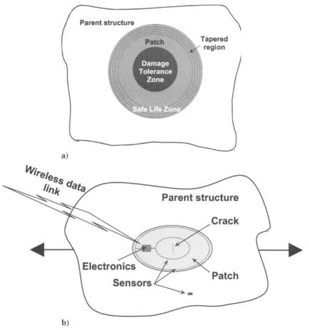
•To detect disbond growth in the safe-life zone of the patch (Fig. 15.2a), which is unacceptable because damage can grow very quickly
•To monitor damage growth in the damage-tolerant zone, where damage growth is stable and slow
Damage in the damage-tolerant zone may consist of either cracks or delaminations in the parent metallic or composite structure and also disbonds in the adhesive or delaminations in the patch system. Current research7 is focused on the assessment of new sensing techniques and sensors, which may be incorporated in bonded repair systems, to detect and monitor disbonds in the adhesive layer, delamination in the patch system, quality of the bond, and crack growth rates in the underlying metallic substrate.
534 COMPOSITE MATERIALS FOR AIRCRAFT STRUCTURES
fiber is considered as an elastic inclusion within the host, and therefore the interaction between this inclusion and the host needs to be considered when interpreting data from the sensor. For example, a significant difference has been observed between the sensitivity of embedded and surface mounted metal-coated optical fibers.11
Rugged and non-intrusive connection systems for optical fiber sensors are required for these systems to be accepted. Therefore, either embedded optical fiber connectors and/or (embedded) wireless communication systems will need to be installed, allowing robust connection on demand without interfering with the measurand.
One of the earliest uses of optical fiber systems was to detect impact damage and monitor damage growth in aramid fiber/epoxy in the leading edge of the DASH-8 aircraft) 2 In this case, special sensitized optical fibers were embedded within the composite leading edge that was fractured after an impact event that exceeded a certain threshold value. The fibers only fractured within the immediate vicinity of the impact site. Thus, when HeNe laser light was transmitted through the fiber, light was emitted from the fiber-fractured ends. Thus, the impact sites were observed visually by significant leakage of laser radiation at these sites. Without treatment, these silica optical fibers can withstand significant shear and in-plane stresses sustained during impact damage without breaking; these fibers break at much higher strains ( ~ 5%) than do most structural materials. Therefore, the most difficult aspect of this technique is in the application of surface treatments that sensitize the fiber to break at a given consistent strain level.
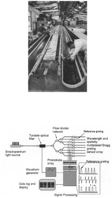
Fiber Bragg grating sensors (see Appendix A) provide a quasi distributed, non intrusive, accurate, and reliable measurement of temperature, strain, and pressure. A fiber Bragg grating system was used on the DC-XA prototype13 (Delta Clipper experimental advanced re-usable rocket program) to monitor loads on ground tests and during takeoff of several highly stressed components. The system enabled the ground personnel to achieve readily understood (in graphical format) load and temperature distributions of the advanced structural components in the vehicle.
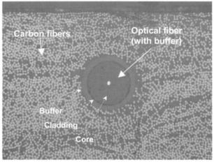
A successful application of the fiber Bragg grating system has been applied to yacht composite masts x4 where 60 optical fiber strain sensors were embedded in 12 separate optical fibers at various locations throughout the rig. Figure 15.4 shows the optical fiber Bragg grating sensors being embedded in the carbon/ epoxy masts during fabrication. A total of 43 sensors were monitored in real time, at a rate of about 500 times per second, with most sensors measuring strains within the range of 3500 Ize and some sensors measured extreme strains (_+ 15,000 Ize). The system was constructed using several optical fibers and a demodulation system with several channels in parallel, which were multiplexed electronically (Fig. 15.5). These systems have been successfully used to monitor loads in the mast for design information (allowing reduced weight, size, and cost) and to enable optimal safe performance during race conditions.
SMART STRUCTURES |
537 |
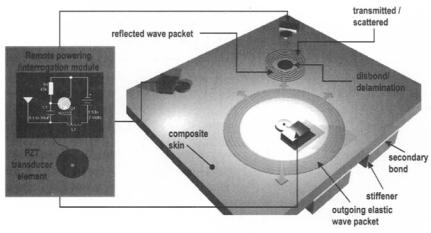
knowledge of the likely location of damage initiation and should therefore allow for a lower sensor density where large structures are considered. The broader sensitivity range also provides a better basis for the quantitative assessment of disbond growth. Some examples on the application of the stress-wave technique are given in the following.
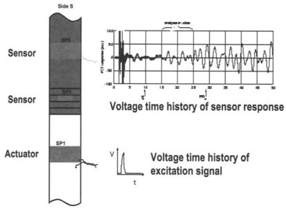
Studies on composite bonded repairs have shown the excellent sensitivity of the stress wave technique to detect disbonds in secondary bonded joints.7 In this study, the approach was to excite elastic stress waves in the host by applying a short voltage pulse to a piezoelement, SP1, surface-mounted to the metal substrate some distance from the patch edge as shown in Figure 15.7a. Part of the elastic energy is transmitted through the bond-line into the patch and received at the two piezoelectric sensor locations (SP2, located on step 3 of the patch, and SP3, located on the far-field region of the patch). Damage in composite bonded repairs was assessed by monitoring the transmitted sensor power (P) within a prescribed time window. The response at sensor SP2, as shown in Figure 15.7b, reflects a high level of sensitivity to disbond growth and correlates well with the strain gauge results.
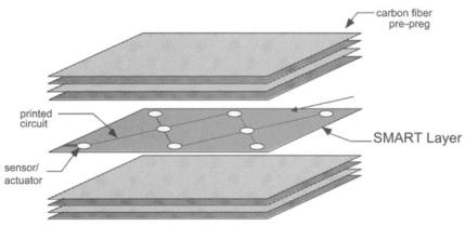
Significant progress has been achieved in the development of the Stanford Multi Actuator Receiver Transduction (SMART) layer that consists of an array of piezoelectric ceramic wafers encapsulated within two layers of Kapton sheets, 15 as shown in Figure 15.8. The Kapton layers incorporate the copper tracks for the electrical connectivity. These SMART layers can be embedded or surfacemounted on the composite component for process control and/or damage detection. One piezotransducer (actuator) generates controlled repeatable diagnostic (acousto-ultrasonic) signals, and the resulting response is detected by the neighboring piezotransducers. By analyzing the resulting response, an indication of the state of cure (for process control) and size and location of damage sites (for structural health monitoring) can be ascertained. The SMART layer has been incorporated in composite bonded repairs and successfully used to detect and monitor crack growth in the metallic substructure. 16 Alternatively, this SMART layer can be used passively to detect noise from impacts that might occur to alert the operator to impact damage.
Novel acousto-ultrasonic (elastic stress wave) generation and detection techniques were developed to generate 2D maps of damage and failure in composite structures. 17 Phase-delayed multi-element low-profile piezoelectric ceramic actuators were designed and fabricated to generate selected ultrasonic Lamb waves, within carbon/epoxy and glass/epoxy fiber epoxy laminates. The detection of the ultrasonic response was achieved using surface-mounted interferometric optical fiber sensors. Advanced signal processing was then used to detect defects and achieve enhanced images of the defect. A multivariate outlier analysis was used to detect changes in the signal that corresponded to damage, that is, generated the damage index. A visual representation of impact damage was then achieved using a mapping technique. This study also showed that the passive listening mode is also an effective technique to detect impact damage in composite laminates.
540 COMPOSITEMATERIALS FOR AIRCRAFT STRUCTURES
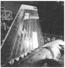
Fig. 15.9 This photograph shows the piezoelectric ceramic actuators, bonded to the carbon/epoxy composite skin of an F/A-18 fin to reduce vibration response of the fin due to buffet loading.
Figure 15.10 shows a comparison of strain density as a function of frequency between the open-loop and closed-loop configurations at the nominal flight condition. From these results, it is estimated (taking into account usage rates) that if the current active buffet load alleviation system were installed on an F/A-18, the increase in life would be approximately 70% or, in other words, 4000 hours could be added to the life of the tail.
15.3.2.2 Damage Mitigation. Shape memory alloy (SMA) wire (See
Appendix A) actuators embedded in a hybrid composite system have been demonstrated to provide active damage control. 19 In this case, the SMA wires were embedded in a composite material, making the SMA wire an integral part of the overall system. The basic approach was to elongate inelastically the SMA fibers before being embedded (the SMA fibers are constrained from reverting to their original length during the curing process). Upon heating the wires beyond their transition temperature (by passing an electric current through them), the wires were activated, causing them to revert to their original length thus changing the stress and strain fields in the specimen. The aim here is to change the stress field around areas of high stress concentration to reduce the effective stress intensity factor and reduce crack growth. This concept was experimentally demonstrated by embedding elongated SMA (nickel-titanium alloy, NiTi) fibers in a photoelastic epoxy material. When the SMA fibers, which were located about 0.5 m m ahead of a crack, were activated, a reduction of 24% in the stress intensity factor was measured. 19 Similar studies were conducted with NiTi fiber/epoxy
542 COMPOSITE MATERIALS FOR AIRCRAFT STRUCTURES
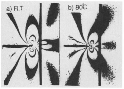
Fig. 15.11 Photoelastic fringe patterns observed at a side notch in a NiTi wire/ epoxy resin specimen loaded at 300 N, at room temperature and 80°C (i.e., with the NiTi wires activated).
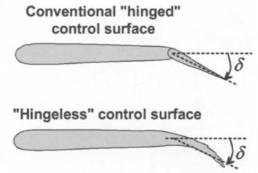
Wing Program investigated incorporating integrated actuation mechanisms, based on SMA and piezoelectric-based actuators, to replace conventional hinged control surfaces to provide variable optimized aerodynamic shapes for a variety of flight conditions.4'22 The concept is shown in Figure 15.12.
Initial activities focused on the development of a SMA torque tube in a 1//6 scale F/A-18 wing to achieve twist within the wing and also SMA wire tendons to actuate the trailing edge. Optical fiber pressure and strain sensors were included in this demonstrator. The demonstrators focused on two variations of the smart wing on a scaled unmanned air combat vehicle, the first incorporating SMA-actuated leading edge and trailing edge control surfaces and the second using an ultrasonic piezoelectric motor to drive a control arm to manipulate the trailing edge. A 30% scale model of an unmanned air combat vehicle was fabricated with one wing using conventional control technologies and the other with smart control surfaces.
The unmanned air combat vehicle consisted of aluminum spars, bulkheads, ribs, and longerons, with glass/epoxy skins. The SMA-based hingeless control surface system used SMA tendons, demonstrated the benefits of this technology compared with conventional designs. However, because of the slow response of the SMA (in seconds), only quasi static conditions could be achieved. In maneuver situations where higher responses are required (i.e., typically require about 60 ° of deflection per second), an actuator with higher bandwidth is