

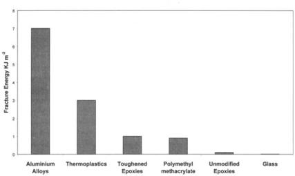
6 COMPOSITE MATERIALS FOR AIRCRAFT STRUCTURES
but it will have much reduced strength and stiffness in other directions--the laminate is then said to be orthotropic.
When the ply configuration is made of equal numbers of plies at 0 °, ___ 45 °, and 90 ° the in-plane mechanical properties do not vary with loading direction and the composite is then said to be quasi-isotropic. A similar situation arises with a 0 ° +__ 60 ° ply configuration. The quasi-isotropic ply configuration is used when in-plane loading is bi-directional. Because the quasi-isotropic configuration has a stress concentration factor (similar to that of an isotropic material), it is also used where local stresses are high, such as in a mechanical joint. However, for most cases, the quasi-isotropic configuration is an inefficient use of the composite material.
1.4Fiber Reinforcements
As described in Chapter 3, continuous strong, stiff fibers can be made from the light elements; carbon and boron, and the compounds silicone oxide (silica and silica-based glasses), silicon carbide, and silicon nitride. Fibers can also be made from organic materials based on long-chain molecules of carbon, hydrogen, and nitrogen. Such fibers include aramid (Kevlar) fibers. Fibers may be available in the form of single large-diameter filaments or as tows (or rovings) consisting of many thousands of filaments. For example, boron fibers formed by chemical vapor deposition (CVD) are produced as single filaments with a diameter of over 100 p~m. Carbon fibers, formed by pyrolysis of a polymer precursor (polyacrylonitrile; PAN), are produced as a filament diameter of about 8 Ixm and supplied in a tow (bundle of filaments) with up to 2.5 x 10 4 filaments.
Chemical Vapor deposition and other techniques can make short ultra-strong and stiff fibers called whiskers. These are filamentary single crystals having diameters in the range 1- 10 Izm and length-to-diameter ratios up to 10,000. With the correct deposition techniques, whiskers can have strengths approaching the theoretical maximum of one tenth of the Young's modulus. This high level of strength results from the perfection of the crystal structure and freedom from cracklike flaws. Whiskers can be made from various materials, including SiC, A1203, C, and B4C.
In the early 1990s, a new form of carbon called carbon nanotubes was discovered. 3 These are essentially sheets of hexagonal graphite basal plane rolled up into a tube, with a morphology determined by the way in which the sheet is rolled up. The tube walls may be made of single or double layers; typically, length is in the range 0 . 6 - 8 nm. They can be produced by a variety of processes, including arc-discharge and CVD. As may be expected, carbon in this form has exceptionally high strength and stiffness. Elastic moduli of over 1000 GPa (1 TPa) and strengths over 100 GPa are quoted, although the minute dimensions and wall geometry of the tubes makes measurement extremely difficult.
INTRODUCTION AND OVERVIEW |
7 |
Whiskers (with some exceptions) are expensive and difficult to incorporate into composites with high degrees of orientation and alignment. So, despite their early discovery, they have not been exploited in any practical composites. Although nanotubes are also expensive and similarly difficult to process into composites, they have such attractive mechanical properties and potential for relatively cheap manufacture that many R&D programs are focused on their exploitation. However, significant technological developments will be required to make composites based on these materials practically and economically feasible.
Textile technology has been developed to produce special reinforcing fabrics from continuous fibers, mainly glass, carbon, or aramid. Small-diameter fiber tows may be woven to produce a wide range of fabrics; simple examples are plain weave or satin weave cloths. Fabrics can also be woven from two or more types of fiber, for example, with carbon fibers in the 0° or warp direction (the roll direction) and glass or aramid in the 90 ° weft direction.
To avoid fiber crimping (waviness) associated with weaving, a textile approach can be used in which the fibers are held in place by a knitting yam. The resulting materials are called non-crimp fabrics, and these can contain fibers orientated at 0°, 90°, and _ 45 ° in any specified proportions. Because of the elimination of fiber waviness, composites based on non-crimp fabric show a significant improvement in compression strength compared with those based on woven materials. Stiffness in both tension and compression is also improved by around 10%.
Fiber preforms ready for matrix impregnation to form the component can be produced by several techniques including weaving, braiding, and knitting. Advanced weaving and braiding techniques are used to produce preforms with 3-D reinforcement, as described in Chapter 14. Three-dimensional weaving is extensively employed for the manufacture of carbon/carbon composites, described later.
1.5Matrices
The matrix, which may be a polymer, metal, or ceramic, forms the shape of the component and serves the following additional functions: 1) transfers load into and out of the fibers, 2) separates the fibers to prevent failure of adjacent fibers when one fails, and 3) protects the fiber from the environment. The strength of the fiber/matrix interfacial bond is crucial in determining toughness of the composite. The interface, known as the interphase, is regarded as the third phase in the composite because the matrix structure is modified close to the fiber surface. The interface is even more complex in some fibers, notably glass fibers, which are pre-coated with a sizing agent to improve bond strength, to improve environmental durability, or simply to reduce handling damage.
INTRODUCTION AND OVERVIEW |
9 |
linking. The processes used to manufacture components |
from thermosetting |
polymer composites are described in detail in Chapter 5 and include:
•Impregnating a fiber preform with liquid resin, which is then cured (resintransfer molding; RTM). This process requires the resin to transition through a period of low viscosity (similar to light oil).
•Infusing a melted resin film into a fiber preform under pressure and then curing (resin-film infusion; RFI).
•Pre-impregnating fiber sheet bundles or tows with a "staged" liquid resin (prepreg) for subsequent arrangement (stacking) followed by consolidation and cure under temperature and pressure.
Epoxies have excellent mechanical properties, low shrinkage and form adequate bonds to the fibers. Importantly, they pass through a low-viscosity stage during the cure, so allow the use of liquid resin-forming techniques such as RTM. Epoxy systems curing at 120 °C and 180 °C have respectively upper service temperatures of 100°C and 130-150°C.
Bismaleimide resins (BMIs) have excellent formability and mechanical properties similar to epoxies and can operate at higher temperatures; however, they are more costly. BMI systems curing at about 200°C have upper service temperatures above 180 °C.
High-temperature thermosetting polymers such as polyimides, curing at around 270°C, allow increases up to 300°C. However, they are even more expensive and much more difficult to process.
Thermosetting materials generally have relatively low failure strains. This results in poor resistance to through-thickness stresses and mechanical impact damage that can cause delaminations (ply separations) in laminated composites. They also absorb atmospheric moisture, resulting in reduced matrix-dominated properties in the composite, such as elevated temperature shear and compressive strength. Recent developments have resulted in much tougher thermoset systems, some with improved moisture resistance, through modifications in resin chemistry or alloying with tougher polymeric systems, including rubbers and thermoplastics.
Thermoplastic polymers, linear (none-cross-linked) polymers that can be melted and reformed, are also suitable for use as matrices. High-performance thermoplastics suitable for aircraft applications include polymers such as polyetheretherketone (PEEK), application approximately to 120°C; polyetherketone (PEK), to 145°C; and polyimide (thermoplastic type), to 270°C. Thermoplastic polymers have much higher strains to failure because they can undergo extensive plastic deformations resulting in significantly improved impact resistance.
Because these polymers are already polymerized, they form very high viscosity liquids when melted. Thus fabrication techniques are based on processes such as resin-film (or resin-fiber) infusion and pre-preg techniques. The main approach is to coat the fibers with the resin (from a solvent solution) and
10 COMPOSITEMATERIALS FOR AIRCRAFT STRUCTURES
then consolidate the part under high temperature and pressure. Alternatively, sheets of thermoplastic film can be layered between sheets of dry fiber or fibers of thermoplastic can be woven through the fibers and the composite consolidated by hot pressing.
Because thermoplastics absorb little moisture, they have better hot/wet property retention than thermosetting composites. However, they are generally more expensive and are more costly to fabricate because they require elevatedtemperature processing. In addition, with improvements in thermosets, even the toughness advantage is being eroded. There is little doubt that thermoplastics will be used extensively in the future for aircraft structures, particularly in areas subject to mechanical damage.
1.5.2 Metals
The light metals, magnesium, aluminum, and titanium alloys (including titanium aluminides), are used to form high-performance metal-matrix composites.4 These materials offer the possibility of higher temperature service capabilities--approximately 150°C, 300°C, 500°C, and >700°C, respectively--and have several other advantages, as discussed later, over polymer-matrix composites. However, these advantages are offset by more costly, complex, and limited fabrication techniques.
Metals often react chemically with and weaken fibers during manufacture or in service at elevated temperatures, so translation of fiber properties is often poor. The tendency for a metal to react with the fiber is termed fiber/matrix compatibility. Generally, because of compatibility problems, ceramic fibers such SiC, A1203, and Borsic (boron fibers coated with silicon carbide) are most suited for reinforcing metals. However, carbon fibers may be used with aluminum or magnesium matrices, provided that exposure to high temperature is minimized.
Methods based on infiltration liquid metal have many advantages for aluminum, provided damaging chemical interaction between the metal and fibers does not occur and the metal is able (or is forced under pressure) to wet the fibers. The process of squeeze casting is attractive because time in contact with liquid metal is limited, minimizing chemical interaction, and the high pressure overcomes wetting difficulties. Another major advantage of this process is that alloys other than casting alloys can be employed. If the fiber does not react readily with molten metal but is easily wetted, for example, silicon carbide fibers in aluminum, more conventional casting techniques such as investment casting may be used. Conventional casting has the major advantage that the size of the component that can be formed is much less limited and requires only simple equipment. Even carbon fibers can be used if the casting process is very rapid, particularly if the fibers are coated with a barrier layer such as silicon carbide, thus minimizing reaction with the molten metal.
INTRODUCTION AND OVERVIEW |
11 |
|
T a b l e 1 . 4 C o m p a r i s o n |
o f C a r b o n / E p o x y w i t h T a b l e 1 . 1 a n d C o n v e n t i o n a l |
|
A l u m i n u m |
A l l o y s f o r A i r f r a m e A p p l i c a t i o n s |
|
•Weight Reduction
-saving 15-20% compared with aluminum alloys
-cost of reduction $60-$100 per kg
-reduction in number of joints
•Performance
-smoother, more aerodynamic form
- improved aeroelastic properties
-more resistant to accoustic environment
-more resistant to service environment
-improved fire containment
-improved crash resistance
-improved stealth properties
• Acquisition Cost
- m a t e r i a l c o s t i n c r e a s e
-reduction due to high conversion rate (low fly-to-buy ratio)
-reduction due to reduction in joints
- f a b r i c a t i o n c o s t g e n e r a l l y i n c r e a s e s
•Repair Costs
-fatigue resistant, reduction
-corrosion immune, reduction
-fretting resistant, reduction
- |
i m p a c t s e n s i t i v e , i n c r e a s e |
- |
p r o n e to d e l a m i n a t i o n , i n c r e a s e |
Diffusion bonding can be employed to produce metal-matrix composites. Fibers are melt-coated, plasma is sprayed or interleaved with metal foil and then hot pressed. However, other than for the larger-diameter fibers such as boron and silicon carbide, excessive fiber breakage resulting from the high mechanical pressures used is a major problem with this approach. Additionally, if high temperatures are required to encourage metal flow, weakening o f the fibers b y solid-state chemical interactions is difficult to avoid.
Fibers can be coated by electrodeposition or C V D to provide a continuous reinforced matrix without the need for subsequent consolidation (pressure). These approaches are much less severe than liquid metal or diffusion bonding and m a y be attractive for some applications. However, the range o f alloys that can be produced by this route is limited, and the high-temperature properties o f the matrix m a y be poor.
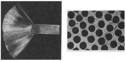
The formation o f a metal-matrix composite by hot pressing coated fibers is illustrated clearly in Figure 1.5, which shows an early metal-matrix composite silica fiber-reinforced aluminum, developed in the mid-1960s by Rolls Royce.5 The fibers are first individually coated with aluminum and then the coated fibers are hot pressed at a temperature o f around 500 °C and a pressure o f 60 MPa. In the example shown for illustrative purposes, only half of the sample has been consolidated.
1.5.3Ceramics
For much higher temperatures than can be achieved with polymer or metal matrices, the options are to employ a silica-based glass; a ceramic such as silicon
12 COMPOSITE MATERIALS FOR AIRCRAFT STRUCTURES
Fig. 1.5 Photograph of a (half) hot-pressed silica fiber/aluminum matrix composite, and (right) microstructure of consolidated side showing fibers, aluminum matrix, and boundary between original fiber coatings. Taken from Ref. 5.
carbide, silicon nitride, or alumina;6 or a carbon matrix. These are called ceramicmatrix composites (CMCs).
In the case of the high-modulus ceramic matrices, the fibers provide little stiffening; their purpose is to increase toughness. This is achieved mainly by blunting and deflecting cracks in the matrix and contributing to increased fracture energy through the various energy-absorbing mechanisms, such as crack bridging and fiber pull-out.
Several techniques are used to form composites with ceramic matrices. These include infiltration of aligned fibers by 1) CVD, 2) impregnation of fibers with a fine powder and consolidating, and 3) impregnation of fibers with a liquid ceramic precursor, generally a polymer, and converting to ceramic at elevated temperature. The powders may be added to the aligned fibers or fiber preforms by injection molding or by sol-gel techniques. Densification of powder coatings may be achieved by hot-pressing, sintering, hot isostatic pressing, or superplastic forging. In most respects, the precursor route is the most promising for ceramics because dense matrices can be produced at low temperatures without causing fiber damage, and complex components can be formed directly.
Glass and glass-ceramic matrices are readily formed by consolidation of fiber preforms impregnated with fine powders applied from a dispersion or gel. The glass melts easily and flows between the fibers to form a continuous pore-free matrix. The procedure is similar to that adopted for thermoplastic matrix composites. In glassceramic matrices, the matrix may subsequently be crystallized by heat treatment, greatly enhancing performance at elevated temperatures.
Carbon matrices may also be formed by CVD of carbon from high-carbon content gases, such as methane, propane, and benzene into a fiber preform. They can also be formed by liquid phase impregnation of fibers followed by pyrolytic
INTRODUCTION AND OVERVIEW |
13 |
decomposition of a precursor with a high carbon content. Suitable precursors include phenolic resin, pitch, and tar-based materials, all of which can have over 40% yield of carbon on pyrolysis. The fibers are generally carbon and the composite called carbon/carbon. Silicon carbide fibers are also used in some applications as an alternative to carbon, particularly where improved resistance to oxidation is required.
With the resin-based route, standard polymer-matrix composite manufacturing processes, such as filament winding or braiding, can be used before pyrolysis.
The precursor route is the most efficient for making carbon matrix composites; however, multiple impregnations and pyrolysis steps are required to produce a matrix with an acceptably low porosity level. This is a slow process resulting in high component costs. The CVD process is even slower, therefore it is mainly used to fill-in fine interconnected near-surface voids in composites produced by pyrolysis. The CVD is, however, suited to manufacture of thin-wall components.
PMCs are extensively used in aerospace structures; however, carbon/epoxy is by far the most exploited so is the main focus of this book. Some current airframe applications are described in Chapter 12. Based on the drivers set out in Table 1.1, a comparison of carbon/epoxy with conventional aluminium alloys is provided in Table 1.4.
1,6 PolymerMatrix Composites
The nomenclature used in the U.S. identifies the composite in the format fiber/ matrix. For example, the main composites discussed in this book are carbon fibers in an epoxy resin matrix and are referred to as carbon/epoxy or graphite/epoxy (also c/ep and gr/ep). Other common composite systems are carbon/BMI, carbon/polyimide, glass/epoxy, aramid/epoxy, and boron/epoxy . This notation can readily be expanded to specific composite systems; for example, a well-known commercial composite system, Hercules AS fibers in a 3501-6 epoxy resin matrix, is AS/3501-6. In the U.K. the terminology for carbon/epoxy is carbon fiber reinforced epoxy, or more usually, carbon fiber reinforced plastic (CFRP).
1.7 Non-polymericComposite Systems
In this section, some of the important non-polymeric composite systems are briefly discussed.
1.7.1 Metal-Matrix Composites
Metal-matrix composites (MMCs), 4'7'8 with continuous or discontinuous fiber reinforcement have been under development for well over 30 years, but have yet to be widely exploited.
The main MMCs based on continuous fibers, and their advantages and disadvantages compared with PMCs, are listed in Table 1.5. Potential aircraft
14 COMPOSITE MATERIALS FOR AIRCRAFTSTRUCTURES
|
T a b l e 1 . 5 |
C a n d i d a t e C o n t i n u o u s |
F i b e r M M C s |
C o m p a r e d w i t h P M C s |
• |
Promising Systems |
|
|
|
- |
boron/aluminium |
alloy; silicon carbide/aluminum; |
alumina/aluminum |
|
- |
silicon carbide/titanium; silicon carbide/titanium aluminide |
|||
- |
carbon/aluminum; |
carbon/magnesium |
(only for space applications) |
|
•Advantages
-higher temperature capability, particularly titanium and titanium aluminide
-higher through-thickness strength, impact damage resistant
-higher compressive strength
-resistant to impact damage
-high electrical and thermal conductivity
•Disadvantages
-limited and costly fabrication technology
- difficult and inefficient joining technology
-limited in temperature capability by fiber/matrix chemical incompatibility
-prone to thermal fatigue: fiber/matrix expansion mismatch problem
-prone to corrosion, particularly with conducting fibers
applications of the MMCs include engine components, such as fan and compressor blades, shafts, and possibly discs, airframe components, such as spars and skins, and undercarriage components, such as tubes and struts.
Carbon/aluminum alloy and carbon/magnesium alloy composites are particularly attractive for satellite applications, including aerials and general structures. These MMCs combine the high specific properties and low, thermal expansion coefficients exhibited by the PMCs together with the advantages indicated in Table 1.5. For example, high conductivity serves to minimize thermal gradients, and therefore distortion, when a space structure is subjected to directional solar heating.
However, MMCs based on carbon fibers, although potentially low-cost, suffer several drawbacks for non-space applications. These include oxidation of carbon fibers from their exposed ends at elevated temperature and corrosion of the metalmatrix in wet environments due to galvanic action with exposed fibers. Other potential non-structural applications of carbon/metal composites include 1) carbon/ lead and carbon/copper-tin alloys for bearings, 2) carbon/copper for high-strength conductors and marine applications, and 3) carbon/lead for battery electrodes.
The earliest developed and probably still the most exploited aluminum matrix MMC is boron/aluminum, based on CVD boron filaments. This MMC is used in the tubular structure in the Space Shuttle. In the future, boron/aluminum may be superseded by CVD silicon carbide/aluminum (or silicon carbide coated boron), which has the advantage of much greater resistance to attack by liquid aluminum. The increased resistance simplifies composite fabrication and improves fiber/ matrix compatibility at elevated temperature.
16 COMPOSITE MATERIALS FOR AIRCRAFT STRUCTURES
high-performance carbon or ceramic fibers is not feasible with high-temperature alloy matrices because of severe compatibility problems. Attempts to use barrier layers on fibers, such as metal oxides or carbides, to prevent chemical reaction have been unsuccessful. In addition, due to the high temperatures and mismatch in coefficients of thermal expansion, thermal fatigue would be a serious problem with these composites. A practical, but not very attractive solution because of the poor specific properties, is the use of refractory metal wire as the reinforcement. This approach has the potential to produce turbine blade materials with an additional 100°C capability over conventional superalloys. A promising composite is based on tungsten alloy wires (W-l% ThO2 or W-Hf-C type) in an iron-based (Fe-Cr-A1-Y) matrix. This alloy has relatively high ductility and excellent oxidation resistance requiring no protective coating. However, a coating such as TiC or TiN may be needed on the fibers to avoid attack by the matrix.
Costs of the continuous fiber MMCs are (and almost certainly will continue to be) very high compared with PMCs, and the range of sizes and shapes that can be produced is much more limited. As mentioned previously, MMCs based on aluminum alloy matrices will be strongly challenged for most elevated temperature applications by current and emerging PMCs.
An alternative to the use of "artificial" fiber reinforcement to produce hightemperature MMCs is to use directionally solidified eutectics. Here the reinforcing phase, produced by eutectic (or eutectoid) decomposition, is in the form of aligned platelets or fibers. These "natural" composites have a great advantage in that the matrix and reinforcement are in chemical equilibrium. However, surface energetics can cause the fibers or laminates to form spherical particles over long periods at elevated temperature, destroying the reinforcing effect. In addition, thermal fatigue can cause internal cracking as well as accelerating spheroidizing of the microstructure. Promising systems studied in the past include Co-Ta-C and Ni-Ta-C.
1.7.2 Particulate MMCs
Particulate MMCs should be mentioned in this overview because they may have extensive aerospace applications 1° as structural materials. In these composites, aluminum or titanium alloy-matrices are reinforced with ceramic particles, generally silicon carbide or alumina in the micron range. Because reinforcement is not directional as with fiber-reinforced MMCs, properties are essentially isotropic. The specific stiffness of aluminum silicon-carbide particulate MMCs (A1/SiCp, where the subcript p refers to particulate) can exceed conventional aluminum alloys by around 50% at a 20% particle volume fraction. For comparison, an MMC with inclusion of silicon-carbide fibers at a similar volume fraction will increase its specific stiffness increased by around 100%.
INTRODUCTION AND OVERVIEW |
17 |
The primary fabrication techniques are rapid-liquid-metal processes such as squeeze casting or solid-state powder processes based on hot-pressing. Particulate MMCs also have the considerable cost advantage of being formable by conventional metal-working techniques and possibly super-plastic forming and diffusion bonding in the case of titanium-matrix systems. However, because of their high wear resistance, special tools such as diamond-coated drills and diamond-impregnated grinding wheels are required for machining.
When fabricated using clean high-grade particles with low porosity and moderate particulate volume fraction, particulate MMCs have high strength, acceptable fracture toughness, and good resistance to fatigue crack propagation.
The MMCs also have high stiffness and wear resistance compared with conventional alloys. They are therefore suited to small components requiring high stiffness combined with fatigue and wear resistance.
1.7.3 Ceramic-Matrix Composites
Ceramic-matrix composites (CMCs) 6 summarized in Table 1.6, offer the main long-term promise for high-temperature applications in gas turbine engines and for high-temperature airframe structures, although there are formidable problems to be overcome. The main requirement is for lightweight blades able to operate uncooled in environments around 1400°C.
The main limitation is the unavailability of fibers with high-elastic moduli and strength, chemical stability, and oxidation resistance at elevated temperatures. For suitable reinforcement of ceramic matrices (such as alumina and silicon carbide or silicon nitride), the fiber must have high oxidation resistance at high
T a b l e 1 . 6 C a n d i d a t e M a t r i x C o m p o s i t e s - - - A d v a n t a g e s a n d D i s a d v a n t a g e s C o m p a r e d w i t h P M C s
•Systems
-silicon carbide/glass; silicon carbide silicon nitride
-carbon/carbon; carbon/glass
-alumina/glass
•Advantages
- high to very high temperature capability (500-1500 °C )
-resistant to moisture problems
-low conductivity
-low thermal expansion
-resistant to aggressive environments
•Disadvantages
-fabrication can be costly and difficult
-joining difficult
-relatively low toughness
-matrix microcracks at low strain levels
18 COMPOSITE MATERIALS FOR AIRCRAFT STRUCTURES
temperature because microcracking of the ceramic allows contact between the fibers and the external environment. The fiber must also be chemically compatible with the matrix and must closely match it in its coefficient of thermal expansion. Thus, the use of similar materials for both components appears to offer the most promise, for example, silicon-carbide-fibers/silicon-carbide- matrix or alumina fibers/alumina matrix. 11 Unfortunately, available fibers either do not maintain strength at high enough temperatures or (in the case of carbon fibers, for example) have adequate oxidation resistance to provide anywhere near the full exploitation of the potential benefits.
CMCs are sometimes based on three-dimentional fiber architectures because in many (but not all) applications, the fibers are required to provide toughness, including through-thickness toughness, rather than stiffness as required in other classes of composites. Thus, for some CMCs, the relatively low fiber volume fraction resulting from this form of construction is not a major limitation.
Glass and glass-ceramic matrices are promising for applications at temperatures around 500°C because of their excellent mechanical properties and relative ease of fabrication. In contrast to CMCs based on conventional ceramics, such as silicon carbide, the low modulus matrix can be effectively stiffened by suitable fibers and relatively high toughness achieved (typically, an increase of over 30 times the matrix glass alone). Because the matrix does not microcrack at relatively modest strain levels and temperatures, carbon fibers can be used. However, for higher-temperature applications more oxidation resistant fibers such as silicon carbide fibers must be used.
Carbon/carbon composites12have no significant chemical or thermal expansion compatibility problems. However, unless protected, they are also prone to rapid attack at elevated temperature in an oxidizing environment. Even where oxidation is a problem, the composites can be used where short exposures to severe applications at temperatures over 2000°C are experienced, for example, in rocket nose-cones, nozzles, and leading edges on hypersonic wings. In the presence of oxygen-reducing conditions, for example with a hypersonic engine running slightly rich on hydrogen fuel, operations for prolonged periods can be maintained. Carbon/carbon composites could be used for prolonged periods at elevated temperature, above 1600 °C, if effective oxidation-preventativebarrier coatings were available. This is a topic of considerable research interest because this composite has the best structural capability of any material at the highest operation temperatures when compared on a specific strength, creep-resistance, or stiffness basis.
Some oxidation barriers include silicon carbide or silicon nitride coatings, which provide an oxidation-resistant outer layer over an inner glass layer; the glass can flow into cracks to seal the coating against oxygen penetration. This approach is called self-healing. An inner oxidation-resistant layer may also be used under the glass layer. The refractory layers are applied by CVD or by dip coating, from a liquid or sol-gel precursor. This coating is applied after producing, in the case of the inner layer, a thin tie (coating anchor) layer on the surface of the composite by reaction with, for example, boron or silicon.
INTRODUCTION AND OVERVIEW |
19 |
A more sophisticated approach to self-healing is to use glass-forming siliconand boron-based particulate materials in the carbon matrix, which reacts with oxygen to form a glass. The glass flows into cracks, sealing them off from oxygen penetration. More sophisticated approaches involve the inclusion of organic compounds in the matrix precursor materials to inhibit oxidation. If successful barrier layers could be developed, carbon/carbon could be used extensively in gas turbines and in the airframes of future hypersonic aircraft.
Finally, carbon/carbon is widely used for aircraft brake disk pads, where its combination of low weight, high-temperature capability, thermal conductivity, and excellent wear resistance results in considerable weight savings.
1.8 HybridMetal/PMCComposites
Structural metals, such as aluminum alloys and composites, including carbon/ epoxy, have a variety of advantages and disadvantages for airframe applications. For example, metals are prone to fatigue cracking but PMCs are not; PMCs are easily damaged by low-energy mechanical impacts but metals are not. Thus, the potential exists to combine these materials in such a way as to get the best of both materials.
One such approach is the aluminum/fiber composite hybrid laminate, 13which consists of thin sheets of aluminum alloy bonded with a fiber-reinforced adhesive. When a crack grows through the metal, the fibers, which are highly resistant to fatigue damage, are left spanning or bridging the crack in its wake (Fig. 1.7). The result is a reduction in crack growth rate by approximately one order of magnitude and an insensitivity to crack length. However, the fibers have little influence on crack initiation and, indeed, because the hybrid composite has relatively low modulus, the increased strain in the aluminum alloy can encourage earlier crack initiation. The fibers also significantly increase the postyield strength compared with unreinforced aluminum alloy, and the composite has a much higher damping capacity.
Disadvantages of these materials include sensitivity to blunt notches due to the inability of the fibers to withstand very high strain levels. Thus, the notch insensitivity of metals is not retained in the hybrid. Also, depending on the reinforcement used, the elastic modulus of the hybrid is generally lower than aluminum alloys, however, this is compensated for by a reduction of specific gravity of between 10-15%. Another problem is cost, which is typically 7 - 1 0 times that of standard aerospace-grade aluminum alloys.
The aluminum alloy is generally either 2024 T3 or 7475 T761, 0 . 2 - 0 . 4 mm thick. The composite is aramid (Kevlar) or glass fibers in an epoxy nitrile adhesive, around 0.2 mm thick for unidirectional reinforcement, or 0.25-0.35 mm thick for (glass reinforcement only) cross-ply. With aramid reinforcement, the laminate is called ARALL (aramid reinforced aluminum laminate), and with glass fiber, GLARE. Because of the sensitivity of aramid fibers to compressive
20 COMPOSITE MATERIALS FOR AIRCRAFT STRUCTURES
r
Fig. 1.7 Schematic diagram of hybrid consisting of thin (~0.4 mm) aluminum alloy sheets bonded with an epoxy film adhesive reinforced with glass or aramid fibers. The fibers are left spanning or bridging fatigue cracks if they develop in the aluminum sheets, vastly reducing the rate of crack growth. Taken from Ref. 13.
stresses and the favorable residual strength that is produced, ARALL may be pre-stretched. This also overcomes, at a cost, the adverse residual stresses arising from the differences in thermal expansion coefficient between aramid, or glass, and aluminum. GLARE does not require pre-stretching as the high-strain glass fiber used is less susceptible to compressive stresses. Consequently, the glass fibers can be cross-plied to give crack growth resistance in two orthogonal directions as may be required for a fuselage structure. Although GLARE has a lower modulus than conventional aluminum alloys, with a reduction of around 20% (particularly with cross-plied fibers), it has the best resistance to fatigue crack growth.
Significant weight savings--20% or so---can be achieved in fatigue-prone regions such as pressurized fuselage skins and stiffeners and lower wing skins by the use of these materials. The hybrid composites are also suited to high-impact regions such as leading edges and inboard flaps and to components subject to mishandling, such as doors.
For applications requiring higher stiffness and strength, as well as a higher temperature, capability studies have been conducted 13 on hybrid laminates made of thin sheets of titanium alloy (Ti-6A1-4V) and a low-modulus carbon fiber composite. The matrix for the composite and adhesive is a thermoplastic (PEEK). This laminate is reported to have excellent resistance to fatigue crack growth as well as good blunt-notch strength.