


516 COMPOSITEMATERIALS FOR AIRCRAFT STRUCTURES
knitting stitches or intermeshed loops is formed by the needle, which, catching the yarn and drawing it through a previously formed loop, forms a new loop. In a knit structure, rows, known as courses, run across the width of the fabric, and columns, known as wales, run along the length of the fabric. The loops in the courses and wales are supported by and interconnected with each other to form the final fabric. Depending on the direction in which the loops are formed, knitting can be broadly categorized into one of two types--weft knitting and warp knitting (Fig. 14.18). Weft knitting is characterized by loops forming through the feeding of the weft yarn at fight angles to the direction in which the fabric is produced. Warp knitting, on the other hand, is characterized by loops forming through the feeding of the warp yams, usually from warp beams, parallel to the direction in which the fabric is produced. These basic knit architectures can be modified through the use of tuck and float loops to achieve specific macroscopic properties in the fabric. In general, the former makes a knitted fabric wider, thicker, and slightly less extensible, and the latter creates the opposite effect, as well as increases the proportion of straight yarns in the structure, which is an important consideration for many composites applications.
Since fibers are required to bend over sharp radii and maneuver sharp comers to form the knitted loops of the structure, knitting may not at first appear to be a manufacturing technique that would be suitable for use in the production of aerospace components. However, the knitted carbon and glass fabric that can be produced on current, standard industrial knitting machines has particular properties that potentially make it very suitable for certain aerospace composite components. Current machinery is also capable of producing preforms with up to four interconnected layers of knitted fabric. Therefore, although the process is not yet able to manufacture preforms with thickness dimensions as large as weaving or braiding, it is still able to produce three-dimensional fiber architectures.
Knit architectures result in a fabric of relatively low strength and stiffness compared with tape or woven cloth, but the knitted fabric is highly conformable
Weft Knit |
Warp Knit |
Fig. 14.18 Schematic diagram illustrating weft and warp knitting.
518 COMPOSITE MATERIALS FOR AIRCRAFT STRUCTURES
stitch density of a particular knit architecture. Nevertheless, the strength of knitted composites in compression is dominated by the properties of the resin.
The strength and stiffness of knitted composites are inferior to woven, braided and unidirectional materials having an equivalent proportion of in-plane fibers. This is due to the limited utilisation of fiber stiffness and strength resulting from the severely bent fibers in knit structures. Similarly, knitted composites are expected to have in-plane properties that are close to those of random fiber mats composites (Table. 14. 2).
Failure of knitted composites is a complex process with the yam crossover points and the curved side legs of the knit loops being critical points at which failure occurs. Substantial microcracking from yam-matrix debonding at these positions within the knitted fabric is also observed during failure.
14.6.1.2 Out-of-Plane Properties. The three-dimensional nature of knitted fabrics is effective in promoting fiber bridging to enhance Mode I fracture toughness where improvements over more conventional composites of up to 10-fold have been observed. These superior Mode I fracture toughness values are reflected in the energy absorption capabilities and impact penetration resistance of knitted composites. As illustrated in Fig. 14.20, under impact conditions, knitted composite materials are found to retain far higher proportions of their undamaged strength when compared with conventional two-dimensional composite reinforcements19.
14.6.2 Applications
The highly looped fiber architecture ensures that knitted fabrics are able to easily undergo significant amounts of deformation when subjected to an external force. Their formability raises the potential of knitted fabric for cost-effective composite fabrication of complex and intricate shapes. This advantage extends to permitting holes in a composite to be formed or knitted in, instead of drilled. As continuous fibers diffuse stresses away from the hole, the strength in the knitted/ formed hole region is increased leading to notch strength and bearing properties
Table 14.2 Typical Mechanical Properties of E-Glass/Vinyl Ester Knitted Composites
Vf ,-~ 55% Courtesy of the CRC-ACS Ltd.
|
Plain knit |
Rib knit |
Milano knit |
Tensile strength (MPa) |
165 |
114 |
135 |
Tensile modulus (Gpa) |
13.6 |
14.3 |
14.8 |
Tensile failure strain (%) |
2.7 |
1.7 |
2.3 |
Compressive strength (MPa) |
138 |
169 |
168 |
Compressive modulus (GPa) |
11.6 |
11.2 |
11.2 |
Compressive failure strain (%) |
1.9 |
2.0 |
1.9 |
|
|
THREE-DIMENSIONALLY REINFORCED PREFORMS |
519 |
|||||
|
1.2 |
|
|
|
|
• |
Uni Tape |
|
|
|
|
|
|
|
|
||
|
|
|
|
|
|
r~Uni Fabric i |
||
|
1 |
A ~ ~ |
× ~ |
Weft Knits |
|
• |
Braid |
|
|
|
|
|
|
× |
×Weft Knits |
|
|
I= |
|
|
|
|
|
|
|
|
== |
0.8 |
|
|
|
|
|
|
|
u) |
|
|
|
|
|
|
|
|
e . |
|
|
|
|
|
|
|
|
.2 |
o.6 |
2 |
|
|
|
°.° |
|
|
|
|
|
|
|
|
|||
E |
0.4 |
|
|
|
|
|
||
o |
|
|
|
|
|
|
|
|
< |
|
|
|
|
|
|
|
|
|
0.2 |
|
|
|
Uni Tape |
|
|
|
|
|
|
|
|
|
|
|
|
|
0 |
|
2 |
4 |
6 |
8 |
|
10 |
|
|
|
|
Incident Energy (J/mm) |
|
|
||
Fig. 14.20 Comparison of normalized retained compression strength after drop weight impact of various E-Glass reinforcements. Vf ~ 55%.
that are relatively a higher proportion of un-notched strength than is the case for composites with a drilled hole. Generally, knitted composites are generally notch-insensitive.
In general, flat knit and shape knit products have so far been used primarily as a demonstration of the ability of the knitting process to manufacture complex shaped components. Jet engine vanes, T-shaped connectors, car wheel wells and aerospace fairings have all been successfully manufactured,7 however the low mechanical performance of the knitted fabric is a deterrent to its wider use.
1 4 . 7 N o n - c r i m p F a b r i c s
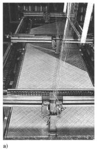
One application of knitting is the subject of intense interest within the aerospace industry. Using warp-knitting techniques in conjunction with fiber placement concepts, multiaxial, multilayer warp-knit fabrics, more commonly known as non-crimp fabrics, can be produced with in-plane fibers that are relatively straight. These in-plane fibers are held in place by a stitched or knitted thermoplastic polymer (typically nylon or dacron) fiber or a flexible high performance fiber such as glass or aramid. The material is not crimped as in the case of woven material, and as such the fibers are arranged in a more optimal fashion (Fig. 14.21). The availability of heavy multi-layered fabric with the
THREE-DIMENSIONALLY REINFORCED PREFORMS |
521 |
advantages. First, unlike multilayer woven preforms, the material affords costeffective off-axis reinforcement. Second, like other multilayer textile preforms, this material has the potential to greatly reduce production cost through reducing the time taken to lay-up the composite component. Finally, this material has the potential to outperform traditional two-dimensional pre-preg tape laminates because it too contains nominally straight fibers but with the added advantage of having through-thickness reinforcement for improved out-of-plane properties. Although stitched two-dimensional laminates can also offer the same attributes, stitching is nevertheless a secondary operation, and there appears to be a general component size and cost restriction with this technique.
14.7.1M-Plane Properties
In general, three-dimensional warp-knit non-crimp composites have slightly inferior in-plane properties when compared with unidirectional pre-preg tape laminates of similar lay-up2° (Table 14.3). The tension control of the throughthickness component is of paramount importance to minimize any out-of-plane crimping (waviness) of the in-plane fiber yams while maintaining good controllability of the preform. Similarly, the yam size and stitch density will determine the degree of in-plane crimping and fiber damage in the load-carrying fiber yams. The presence of any such crimping could render the non-crimp composites inferior under tensile, compressive, and flexural conditions, compared with two-dimensional woven composites. On the other hand, insufficient tension in the through-thickness yams will cause them to buckle under cure pressure and hence, be ineffective at providing a crack closure force.
It should be noted that the in-plane properties could be degraded by the impalement of the non-crimp layers by the knitting needles. This impalement causes fiber distortion and damage, a phenomenon not dissimilar to that observed for stitched composites. A way to eradicate this is to ensure knitting needles are
Table 14.3 Comparison of in-plane mechanical properties for carbon/epoxy tri-axial layups manufactured from two-dimensional unidirectional pre-preg tape and 2 layers of tri-axial non-crimp fabric
|
2-D Unidirectional |
|
|
||
|
Pre-preg Tape |
Non-crimp |
|||
|
[452. - |
4 5 2 , |
[{45, - |
45,0}, |
|
|
06. |
- 452, 452,], |
{0, - 45,45}]s |
||
Test orientation |
0o |
|
90° |
0o |
90° |
Tensile modulus (GPa) |
64.8 |
|
21.4 |
60.8 |
17.2 |
Tensile strength (MPa) |
951 |
|
123 |
621 |
159 |
Compressive modulus (GPa) |
59.9 |
|
19.6 |
54.7 |
16.5 |
Compressive strength (MPa) |
852 |
|
215 |
574 |
236 |
522 COMPOSITE MATERIALS FOR AIRCRAFT STRUCTURES
inserted between tows of in-plane fibers. However, the gaps that are formed between the tows by doing this are potential resin-rich sites that are considered detrimental to some properties.
Microscopic analysis has shown that the knit structure in the non-crimp composite appears effective in constraining the delaminations and longitudinal splitting that are normally associated with unidirectional pre-preg tape laminate. Other than that, it seems that non-crimp and unidirectional pre-preg tape laminates have very similar failure mechanisms, essentially, multiple cracking in off-axis plies and delamination at _+45 ° interfaces.
14.7.20ut-of-PlaneProperties
The interlaminar fracture toughness of non-crimp composites is superior to that of unidirectional pre-preg tapes due to the knitting yarn acting to bridge the crack and restrict its further growth when subjected to out-of-plane loads. In spite of this, little improvement is observed in the suppression of delamination damage due to impact. The damage tolerance of non-crimp and unidirectional pre-preg tape composites is similar, although the former exhibits superior compression-after-impact strengths with increasing impact energy level.
The damage generated in non-crimp composites by low-energy impact is more complex than that in unidirectional pre-preg tape laminates. Instead of a collection of shear cracks linking delamination planes, which is normally observed in unidirectional pre-preg laminates, the impact damage created within non-crimp composites consists of an intricate array of cracks not dissimilar to that observed in more conventional knitted composites. This highly branched cracking links planes of delamination which also contain parallel matrix cracks that appear to coincide with the inter-fiber tow resin-rich regions. The presence of the z-direction reinforcement yarns in the non-crimp fabric should be very effective in reducing the amount of back face spalling compared with unidirectional pre-preg tape laminates. The level of performance improvement in this area would be linked to the mechanical properties of the z-direction yarns.
14.7.3 Applications
There are significant cost incentives to be gained with non-crimp fabric in comparison with unidirectional pre-preg tape composites. These include reduced wastage and labor, adaptability to automation, and virtually unlimited shelf life without the need for refrigeration. Limitations arise from issues such as relatively higher raw material cost, impracticality in terms of ply drop-offs, and restrictions on the number of fabric types available commercially. The overall cost implication is, therefore, an important consideration when deciding between the more traditional unidirectional pre-preg tapes and non-crimp composites. In spite of these issues, a great deal of effort is being devoted within the aerospace industry to develop these fabrics for use within secondary and primary structures