


THREE-DIMENSIONALLY REINFORCED PREFORMS |
501 |
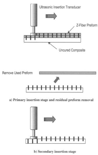
appropriate ultrasonic horn. It is claimed that the ultrasonic insertion technique can be used to insert metallic pins into cured composites, a capability that could be used in the repair of delaminations in composites, although considerable damage to the parent material would result.
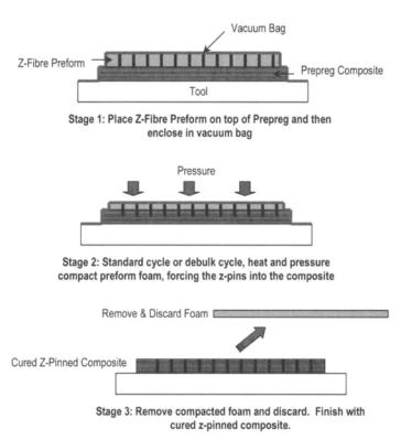
Between the two pin insertion methods, the vacuum bag route is perhaps more suitable when a large or relatively unobstructed area is to be z-pinned. On the other hand, localized z-pinning or difficult-to-access areas are more efficiently achieved using the ultrasonic process by configuring and shaping an appropriate ultrasonic horn.
14.3.1 Mechanical Properties
Relatively little work has been published on the mechanical properties of z-pinned composites. Based on available data,7 it can be deduced that significant improvements in both mode I and mode II fracture toughness are achievable through z-pinning, which in turn translate to superior damage resistance and tolerance,8 and improved skin-stiffener pull-out properties.9 There is evidence9 that these improvements in out-of-plane properties are achievable without much, if any, sacrifice to in-plane properties. Other work, 10however, shows that the pins can introduce excessive waviness to the in-plane fibers, causing compressive properties to be severely degraded. Clearly, in much the same way as in the case of stitching, the degree to which the in-plane properties are detrimentally affected, and the out-of-plane properties are improved, is dependent on the pinning parameters, such as density and configuration.9
14.3.2 Stitching Versus Z-Pinning
Research into the effects of z-direction reinforcement in traditional twodimensional laminates on mechanical properties has been particularly extensive over the past decade or so. The impetus for this research is derived from the potential of stitching, and more recently, z-pinning to fulfil the need for a simple and cost-effective remedy for the poor out-of-plane properties of conventional two-dimensional FRP composites. The amount of z-direction reinforcement required to provide a substantial amount of out-of-plane improvement is small, typically no more than 5%.
The improvements in fracture toughness afforded by the two techniques mean that higher design allowables could be used in the designs of composite structures. In other words, stitched and z-pinned composites can be more readily considered as candidate materials for structures where impact damage (e.g., due to dropped tools), high peel stresses (e.g., in joints and at hard points), and cut-outs (e.g., edges and holes) are difficult to avoid. Stitching and z-pinning also provide the opportunity for parts integration to be incorporated into the pro-
duction of composite components, |
thus improving the ease of handling, |
the potential for process automation, |
and the overall cost-effectiveness of the |
502 COMPOSITE MATERIALS FOR AIRCRAFT STRUCTURES
manufacturing process. Further, when used in conjunction with a liquid molding technique, stitching can provide some pre-compaction of the preform and this can reduce mold clamping pressures required while ensuring a high fiber/volume fraction in the finished product.
A potential benefit of these reinforcement techniques is that post-catastrophic failure, they can hold fragments together--although stitches, compared with z-pinning rods, would be more effective in this respect. This benefit would be especially important in applications such as fan blades in aero engines, where fragments from a fractured blade, if unrestrained, could be swept into the engine and cause further damage. In fact, carbon/epoxy pins are already used in operational General Electric (GE90) fan blades to reinforce areas that require higher strength, and there are plans to increase the level of pinning in the growth version of these blades, la Z-pinning has also been used to produce highperformance sandwich structures. This is achieved by integrally connecting the skins through a foam core. It is claimed that, compared with traditional aluminum honeycomb sandwich structures, Z-pinned cores have three times the crush strength as well as superior damage tolerance. Although z-pinning is still inferior to mechanical fasteners in terms of pull-out failure load, it has good potential as an alternative shear attachment technique because its use would result in lighterweight structures at a lower cost.
Stitching is inferior to z-pinning in three major ways. First, there are practical restrictions on the size and shape of the component that can be stitched, which usually can only be overcome with purpose-built stitching machines that demand large capital costs. Further, z-pinning is more appropriate than stitching for reinforcing regions with small radii of curvature. Second, the wrapping effect of the stitching ya m means that careful tension control has to be exercized so that inplane fibers are not excessively crimped in the thickness direction. Each z-pin is independent of the others and hence does not pose this problem. Finally, to ensure minimal breakage, a limited number of fiber materials can be used as the stitching yam. Alternatively, z-pins can be manufactured from a much wider range of materials, which can have large aspect ratios (I/d) to ensure good traction between the z-direction reinforcement and the base material.
14.4Three-Dimensional Weaving
14.4.1Process
Woven fabrics are made of warp (longitudinal) and weft (transverse) yams interlaced in a regular order on mechanical looms. The process of weaving is already used extensively within the composite industry to produce the vast majority of the single-layer, broadcloth fabric that is currently used as a reinforcement. With minimal modification, the same standard industry mac-
THREE-DIMENSIONALLY REINFORCED PREFORMS |
505 |
looms have been in use since the early 1970s when the first was developed to produce three-dimensional woven carbon - carbon preforms for aircraft brakes. 12 These looms allow complex-shaped structures to be woven in the final shape without the need for folding operations and can produce fabric with yams at angles such as _+45°. Structures of such complexity are often difficult to manufacture using normal pre-preg technology, therefore the use of weaving technology can result in substantial cost savings in the production of complex composite structures.
14.4.2 Mechanical Properties
14.4.2.1 In-Plane Properties. The tensile and compressive properties of 3-D woven composites have been studied since the 1980s, but a clear picture of their in-plane performance and how it is affected by variables such as the weave architecture is still developing.7 Many of the studies on the performance of threedimensional woven composites have been conducted with comparison to twodimensional laminates manufactured with similar, but not always the same, parameters (fiber content, lay-up, etc.), and often these differences have prevented conclusive comparisons of performance being made.
Numerous investigations of the tensile properties of three-dimensional woven composites have led to conflicting results. Some researchers have reported the tensile modulus of three-dimensional woven composites to be reduced in comparison to similar two-dimensional laminates, whereas other researchers have reported an increase. However, in spite of this conflict in the reported results, it has been observed that (in the majority of cases) the tensile modulus of a three-dimensional woven composite is within 20% of the modulus of the comparable two-dimensional laminate. The studies have also shown that the modulus of the three-dimensional woven composite is not significantly influenced by the content of the z-direction reinforcement or the weave architecture. The explanation for the higher tensile modulus of some threedimensional material is thought to be due to a slightly higher fiber content than the comparable two-dimensional laminate. The lower modulus in other cases is generally considered to be due to the increased waviness of the in-plane yams caused by the presence of the z-direction reinforcement.
There is also no conclusive evaluation of the tensile strength of threedimensional woven composites. The failure strength of three-dimensional woven composites has been found to be the same or (more often) less than the strength of a comparable two-dimensional laminate, but the difference is rarely more than 20%. As with tensile modulus, the strength of 3-D woven composites does not appear to be significantly affected by the z-direction reinforcement content or weave structure. The reduction in the tensile strength of three-dimensional woven composites is considered to be primarily due to the increased waviness of the inplane yarns.
506 COMPOSITE MATERIALS FOR AIRCRAFT STRUCTURES
With regard to the compressive properties of three-dimensional woven composites, the modulus is generally reduced due to the z-direction yams causing an increased waviness and local crimping of the in-plane yarns. A comparison of the compression strength of three-dimensional woven composites relative to similar two-dimensional laminates is more complex, and so far the findings have not been conclusive with both improvements and reductions in strength being observed. The compressive strength appears to be independent of weave architecture or the proportion of z-direction fiber. Degradation of the compressive strength is believed to be due to the kinking or microbuckling of the load-bearing yarns, which in turn is attributed to local waviness or crimping of the yarns as a result of the z-direction reinforcement. The occasional observed improvement in strength could be attributed to the initiation of delamination being suppressed by the z-direction yarn.
14.4.2.2 Out-of-Plane Properties. The most significant difference between the performance of three-dimensional and two-dimensional woven composites is apparent when examining their interlaminar fracture properties (delamination resistance) and their impact properties. 7
Most interlaminar fracture studies have been performed in mode I, or tensile crack opening, conditions. The delamination resistance increases with the volume content, elastic modulus, tensile strength, and pull-out resistance of the z-direction yarn, but even a relatively modest amount of z-direction reinforcement can provide a large improvement to the delamination resistance. As with the other forms of z-direction reinforcement (stitching, z-pinning, etc.), the improvement in the delamination resistance occurs by the formation of a bridge of z-direction fibers spanning the crack faces behind the advancing crack tip, which restricts the further growth of the delamination.
The enhanced interlaminar fracture properties translate into improved impact properties. Impact performance has been extensively studied, and it has been found that in comparison with two-dimensional laminates, the improved delamination resistance of the three-dimensional woven composite results in a reduced area of impact damage over a range of impact energies. This superior impact damage resistance usually results in higher post-impact mechanical properties than that obtained from two-dimensional laminates, Fig. 14.12.
14.4.3 Applications
Three dimensional woven composites were used in the Beech StarshipJ 2 Woven H-joint connectors were used for joining honeycomb-sandwich wing panels together. The use of this woven connector was reported to be critical to the cost-effective manufacture of the wing and improved stress transfer at the joint, thus reducing peel stresses.
Three dimensional woven composites are used by Lockheed Martin for the air inlet duct in the F35 military fighter jet. In this example, the stiffeners are
508 COMPOSITE MATERIALS FOR AIRCRAFT STRUCTURES
structure referred to as the preform. Due to the interweaving of the yams, braided preforms have conformability, torsional stability, and structural integrity as well as some degree of three-dimensional reinforcement (depending on the process), making them easy to handle and work with. The braiding process is capable of producing preforms of intricate shape; however, the size and length of the preform is generally limited to the size of the machine and yarn supply, respectively.
The adaptation of braiding to the composites industry has meant extensive research and development of the basic braiding process. This has focused on the hardware, production, and the geometric analysis of the braids, with the ultimate goal of complete automation and integration of machining and composite processing incorporating C A D / C A M (computer-aided design/ manufacture) in aerospace factories.
Braided preform architectures can effectively be classified into two categories: two-dimensional and three-dimensional. Two-dimensional braiding has become well established over the past 15 years in the composites industry with a steadily growing database of knowledge and expertise. In contrast, three-dimensional braiding is still in its infancy.
14.5.1Two-Dimensional Braiding Process
The traditional two-dimensional braiding process can be used to produce preforms of complex tubular shapes or in collapsed form, fiat panels. The process of two-dimensional braiding can perhaps be best visualized by relating it to a maypole dance, in which the yarns are braided over a mandrel by yam carriers that move in an interlinking rotational fashion around the mandrel. The simplicity makes it an efficient and cost-effective process compared with some other textile processes.
The braiding machine, shown schematically in Figure 14.13a, consists of three primary components: 1) yarn or fiber tow carriers, 2) interlinking mechanism and 3) take-up mechanism. The machine set-up involves placing the braiding fiber tow onto spools that are then loaded onto the carriers. The carriers (Fig. 14.13b) comprise a track follower, spool shaft, tensioning mechanism (weights or springs), and let-off mechanism (via hooks, loops, or wheels).
The carriers are connected to the braiding machine through "horndogs" and "horngears," which propel the carriers into their interlinking rotational path as shown in Figure 14.13c. The usual yarn structure resulting from two-dimensional braiding is a simple regular biaxial braid where each yarn or tow in the two bias directions pass over and under two yarns in a repeat. The orientation (or braid angle, Figure 14.14) of these bias yams typically range between 15° and 85 °. By modifying the horngears on the braiding machine, different braid patterns can be achieved. Hollow horngears also allow the introduction of axial yarns in the braid that add to the stiffness of the preform. Two-dimensional braids, which contain longitudinal yams, are referred to as triaxial braids (Fig. 14.14).
THREE-DIMENSIONALLY REINFORCED PREFORMS |
509 |
Movin~beaidlngmachine
|
|
|
a) |
z - " |
Let-off |
|
|
. ~ ^ ~ a n i s m |
|
|
|
! |
|
|
S T E P I |
~ |
|
|
Carriers |
|
Spool |
|
STEP2 ~ ~ |
/ ~ ~ e |
|
||
Tensioning |
|
|
Horngear |
|
|
STEP3 |
|
mechanism |
|
r |
|
|
|
||
|
b) |
|
c) |
Fig. 14.13 a) Schematic diagram of a typical braiding machine; b) typical yarn carrier; c) horngear movement.
To form a continuous preform, a mechanism is also required to pull the fabric as it is formed. This is the take-up mechanism. Although there are several different types of take-up mechanisms, there are basically two systems that are applicable for braids intended for use in the aerospace industry. The first system involves a mandrel mounted on a gantry, allowing the mandrel to move back and forth while the braid is formed as shown in Figure 14.13a. The other system involves fixing the mandrel and allowing the braiding machine to move back and forth.
Research and development into the two-dimensional braiding process has focused on reducing the cost of the process and investigating its limitations and applications. Attempts at reducing the cost have resulted in the development of

THREE-DIMENSIONALLY REINFORCED PREFORMS |
511 |
speeds. Carbon fibers have shown to be more susceptible to damage than aramid or glass fibers.
The mandrel forms an integral part in the fabrication of two-dimensional braided structural preforms. It not only provides the shape of the preform, but can also be used in the consolidation process and may also provide structural benefits. Mandrels may be rigid or flexible and are made from a number of materials such as metals (steel/aluminum), structural foams, and watersoluble or fusible casting compounds.
14.5.3Design of Braided Composites
The design of braided composites needs to take into account the structural requirements of the part in question as well as the manufacturing issues outlined above and the limitations of the braiding process. Techniques used to design the braided preform may involve models that relate the geometric features of the braid architecture to the process parameters. Using such models enables the designer to accurately specify a braided preform with the desired fiber orientations. There is a range of analytical tools that can be used to predict the mechanical performance of the braided composite. Conventional techniques such as classical laminate theory and stiffness averaging have shown to work well in predicting stiffness. However, strength prediction is somewhat more difficult, as is the case for all composite structures. Traditional laminate failure theories do not work because they do not take into account the different failure mechanisms of these materials. Specialized methods that model these mechanisms should be used.
14.5.4 Mechanical Properties
Although the mechanical property database of two-dimensional braided composites is not as large as that for unidirectional tape or two-dimensional woven pre-preg, testing of these materials has shown that their properties compare favorably with other forms of composites. Two-dimensional braided composites have been shown to have similar stiffness and strength values compared with two-dimensional woven composites of similar lay-up. When compared with unidirectional tape, braids have also shown similar elastic properties; however, their strength values are reduced by
as much as 25%. This discrepancy in strength is mainly attributed to the difference in fiber architecture e.g., fiber waviness that causes changes in failure mechanisms, particularly in compression.
With regard to damage resistance and tolerance, two-dimensional braids have been shown superior to both unidirectional and two-dimensional woven composites. Low-energy impacting followed by compression testing has revealed that braided composites can be significantly more resistant and tolerant to

THREE-DIMENSIONALLY REINFORCED PREFORMS |
513 |
Fig. 14.16 Three-dimensional braid architecture. Courtesy Atlantic Research Corporation, Gainesville, VA.
overcome the lack of through-thickness reinforcement with multi-layer twodimensional braids by interlocking the multi-layers with binding yams. This has led to the development of three-dimensional braiding techniques that have provided new possibilities in the development of near net-shape preforms with added through-thickness reinforcement.
The first serious development of three-dimensional braiding, which occurred in the 1960s, was referred to as four-step (or row-and-column) braiding, a term given because of the four distinct operations in the braiding process. Since then other variations have been developed, along with some new techniques yielding three major styles of three-dimensional braiding: four-step braiding, two-step braiding, and multi-layer interlock braiding. Figure 14.16 provides an example of the type of construction that can be achieved with three-dimensional braiding.
Despite its advantages, the use of three-dimensional braiding has been limited. The maximum size of the preform is determined by the braiding machine size, and most industrial machines are only able to braid preforms with small crosssections (less than 100 mm). Extremely large and expensive machines are required to produce preforms large enough for typical aircraft structures. Threedimensional braiding machines are still at the research and development stage, and only a few machines are currently producing commercial preforms.
Three-dimensional braiding was developed in the late 1960s to produce threedimensional carbon/carbon composites (Chapter 1) to replace high-temperature metal alloys in rocket motor components.7 These components achieved weight savings of 30-50% and demonstrated the ability of braiding to produce composite components of complex shape. The various styles of threedimensional braiding can be tailored for specific structural applications and
514 COMPOSITE MATERIALS FOR AIRCRAFT STRUCTURES
can all be accomplished with a range of fiber materials: glass, carbon, aramid, ceramic, and metal. With three-dimensional braiding, it is possible to braid inserts or holes into the structure that have a greater stability than holes that have been machined. The braid pattern can be varied during operation so that a change in cross-sectional shape is possible, including introducing a taper to the preform. Thick-walled tubular structures can also be made by suitable arrangement of the braiding architecture and fiat preforms can be made from these tubular structures by braiding splits into the preform then cutting and opening it out to the required shape. 17 A bend is also possible as well as a bifurcation, which will allow junctions to be produced and these processes even allow 90 ° yams to be laid into the preform during manufacture. This wide range of possible preform shapes makes three-dimensional braiding one of the most potentially versatile ways of producing a three-dimensional fiber reinforced preform.
14.5.7 Mechanical Properties Three-Dimensional Braided
Composites
14.5.7.1 In-Plane Properties. The mechanical properties of threedimensional braided composites have been studied since the 1980s, but in spite of this, the extent of the published literature only constitutes a small part of the information necessary to fully characterize this class of composite material. The current lack of detailed test data and an inadequate understanding of their mechanical behavior is limiting the use of three-dimensional braided composites in aircraft structures.
The most influential factor on the in-plane properties is the angle that the braided yarns (including the axial yarns if present) make with the loading direction. The braiding angle is set by the pattern to which the preform is being braided, and a closer orientation of the yarn to the load direction increases the mechanical properties in this axis but lowers the properties transverse to this direction. A similar result is obtained when some of the braiding yarns are kept fixed in the axial position or extra axial fibers are inserted. Because the braided yarns all travel to the specimen surface in the common three-dimensional braiding processes, any machining of the surfaces will result in the braiding yams becoming discontinuous along the specimen length, with a resultant drop in performance.
Other aspects of the braided preform such as tow size and the type of threedimensional braiding process used to manufacture the preform have also been seen to influence the in-plane properties. 7 When compared with two-dimensional laminates with similar lay-ups and fiber contents, it has generally been observed that three-dimensional braided composites have inferior in-plane properties. This is because, as mentioned previously, the braiding process tends to crimp the yams, lowering their performance relative to tape laminates.