

3 Fibers for Polymer-Matrix Composites
3.1Overview
As a result of their strong directional interatomic bonds, elements of low atomic number, including C, B, A1, and Si, can be formed into stiff, low-density materials. These materials may be made entirely from the elements themselves (e.g., C or B), or from their compounds (e.g., SIC), or with oxygen or nitrogen, (e.g., A1203, SiO 2 or Si3N4).
The strong bonding I also inhibits plastic flow, at least at temperatures below around half the melting temperature. Because these materials are unable to relieve stress concentrations by plastic flow, they are markedly weakened by submicroscopic flaws, particularly those open to the surface. Thus, it is generally only when made in the form of fibers that the inherent very high strength of these materials can be realized. 2'3 There are several reasons for this, including the following:
•The probability of a flaw being present (per unit length) in a sample is an inverse function of volume of the material, as described by Weibull statistics.4 Hence a fiber having a very low volume (per unit length) is much stronger on average than the bulk material. However, the bulk material, having a much higher content of weakening flaws, exhibits a much lower variability in strength, as shown in Figure 3.1. It follows similarly that the smaller the fiber diameter and the shorter the length, the higher the average and maximum strength, but the greater the variability.
•Flaws can be minimized by appropriate fiber manufacturing and coating procedures to minimize surface damage. Also, the precursor materials used in fiber making must be of a high purity, including freedom from inclusions. The effect of flaws on strength can be estimated from thermodynamic (energy balance) and elasticity considerations.
•Fiber manufacturing processes that involve drawing or spinning can impose very high strains in the direction of the fiber axis, thus producing a more favorable orientation of the crystal or atomic structure.
•Some fiber manufacturing processes involve a very high cooling rate or rapid molecular deposition to produce metastable, often ultra-fine grained structures, having properties not achievable in the bulk material.
55
56 COMPOSITE MATERIALS FOR AIRCRAFT STRUCTURES
===
co
•- Bulkmaterial
O
5
Z
~ Fibrous
Load
Fig. 3.1 Effect of sample cross-section on distribution of strength. 4
Polymeric materials, based on a suitable carbon backbone structure, can also form strong, stiff fibers. Some of these materials rely on a very high drawing ratio to orientate the polymer chains, as well as high purity to develop their stiffness and strength.
Finally, some polymeric fiber materials can be used as precursors for producing inorganic fibers, through a process of controlled pyrolysis.
Thus, commercially available continuous fibers used in structural polymermatrix composites (PMCs) for aerospace applications can be loosely classed as ceramic or as polymeric. Ceramic fibers, for the purposes of this discussion, include silica, carbon, and boron, although strictly these last two are not classed as ceramics. True ceramic fibers include silicon carbide and alumina, whereas polymeric fibers include aramid and high-density polyethylene.
Ceramic fibers, including glass, are typically flaw-sensitive and fail in an elastic brittle fashion from surface or internal flaws and inclusions.
Polymer fibers exhibit a complex fibrous type of fracture, as they essentially are made of a bundle of relatively weakly bonded sub-filaments or fibrils. As a result these fibers, compared with the ceramic fibers, are relatively insensitive to flaws. However, under compression loading they can defibrillate, resulting in poor compression properties.
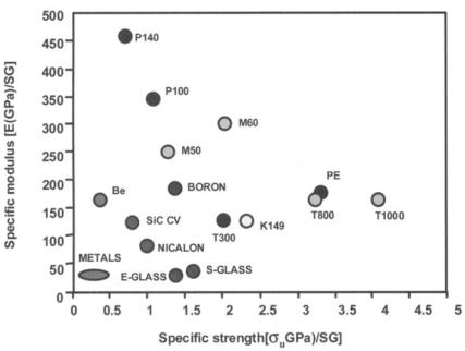
Figure 3.2 summarizes the specific properties of several fiber types and includes, for comparison, structural metals. As a result of fiber volume fraction
58 COMPOSITE MATERIALS FOR AIRCRAFT STRUCTURES
!
°~
O O
0
r~
~ |
|
o |
§ |
|
|
A |
A ~ " |
" |
|
~ × |
I I |
I I |
I I I |
I |
|
||||
r~3 |
r~ |
|
|
|
" , ~
e~
~,.- o |
~ ~ ~ . ~ . ~ = = = |
~ |
FIBER S FO R P O L Y M E R - M A T R I X C O M P O S I T E S |
59 |
-5
.9
E
o
o
[ . .
o
..=
©
©
r~
I
[-.,
=..
z
60 COMPOSITE MATERIALS FOR AIRCRAFT STRUCTURES
dielectric properties, glass-fiber PMCs are also widely used in applications in which transparency to electromagnetic radiation is required, including radomes and aerial covers.
Glass is an amorphous solid produced by cooling a viscous liquid at a sufficiently high rate to prevent the formation of ordered or crystalline regions. Compounds that make up the glass in glass fibers can include (in addition to silica) oxides of aluminum, boron, calcium, magnesium, sodium, and potassium. Additives are used to lower the melting point of silica so that the required viscosity is obtained at a lower temperature. In addition, they facilitate the removal of gas bubbles and have a significant effect on the mechanical and chemical properties of the final product.
Glass fibers are manufactured by a viscous drawing process depicted in Figure 3.3 in which glass, melted in a furnace at temperatures of about 1400 °C, flows into an electrically heated platinum-rhodium alloy bushing or spinneret, containing a large number (400-8000) of holes in its base. The emerging glass drops are drawn into fibers by pulling at speeds of up to 50 m s . - 1 They are then cooled by a fine water spray and coated with a size by contact with a rotating applicator. Finally, the fibers are combined into a strand as they are wound onto a take-up spool.
The fiber diameter, typically around 5 - 2 0 Ixm, is a function of the size of the holes in the bushing, the viscosity of the melt (which is dependent on the composition of the glass and the temperature), the head of glass in the furnace, and the rate of winding. Depending on the number of holes in the bushing, the strand typically consists of 52, 102, or 204 fibers.
The cooling rate experienced by the fibers is very high, > 10,000 °C s -1. A parameter5 called thefictive temperature is the apparent temperature at which
Drawing of glass filaments (A)
|
| |
|
I I -- spinninghole |
gloss melt feed |
| |
bushing |
|
approx. 1250°C |
,J |
spinning holes |
molten glass |
|
|
approx, 1250*C |
|
|
|
|
rapid cooling |
|
|
filaments cooling |
drawing at high |
|
|
|
|
|
|
|
speed |
|
|
size |
|
Q |
|
assembler |
The formation of a single |
|
|
||
|
strand |
filamenl according to the |
|
|
traversing and |
process shown in A. |
winding
Fig. 3.3 Schematic illustration of the process used to manufactureglassfibers.
FIBERS FOR POLYMER-MATRIX COMPOSITES |
61 |
the glass is frozen, generally found to be 2 0 0 - 3 0 0 °C above the |
liquidus. |
As a result, the fiber structure is somewhat different from that of bulk glass, resulting in a higher tensile strength but lower elastic modulus and chemical resistance.
3.2.2Effect of Flaws
Glass fibers, being essentially monolithic, linearly elastic brittle materials, depend for their high strength on the absence of flaws and defects. These take the form of sub-microscopic inclusions and cracks The inclusions can often be seen with a scanning electron microscope, but "cracks" sufficient to reduce strength significantly can be very difficult to find because they are of nanometre dimensions. The origin of flaws is, however, generally obvious when examining the fracture surface because growth starts from the region of the flaw as a flat (mirror) surface and transforms to hackles radiating from this region as growth accelerates.
Commercial glass fibers are particularly prone to the formation of flaws by abrasion against other fibers, resulting in a reduction in strength of the order of 20% compared with pristine fibers made under laboratory conditions.
The tensile strength is probably significantly dependent on the composition, structure, and internal stresses in the surface layer, all of which differ significantly from those in the internal structure due in part to the high cooling rate. Although this layer is only of the order of a nanometer thick, it is of the order of the size of the flaws that control the strength of high strength fibers > 2 GPa. Generally, surface flaws have a similar strength-reducing effect compared with internal flaws of twice the length.
Humid environments reduce the strength of glass fibers under sustained loading, as the moisture adsorbed onto the surface of the flaw reduces the surface energy, thus facilitating slow growth to critical size. This phenomenon in glass is called static fatigue.
The strength of the glass fibers is reduced by about a further 50% when they are formed into a polymer-matrix composite. However, because of the bundle effect described in Chapter 2, this reduction is not noticeable. Essentially, the gauge length for a bundle of fibers is the length of the bundle, whereas, due to load transfer from the matrix, for a composite it is only of the order of 1 mm, depending on fiber diameter and fiber/matrix bond strength. Further reductions in strength can occur if the composite is exposed to wet conditions because components leached out of the polymer can cause acidic or basic conditions to develop at the fiber surface.
3.2.3Types of Glass Fiber
The compositions of glass made into fibers for PMCs are listed in Table 3.2 There are two types of glass fiber used for structural applications: "E," a calcium
62 COMPOSITE MATERIALS FOR AIRCRAFT STRUCTURES
alumino-borosilicate glass, and "S," a magnesium alumino-silicate glass. E stands for electrical grade, because compared with other standard forms of glass, its electrical resistivity is high and its dielectric constant low. These are by far the most widely exploited in structural applications, particularly in the non-aerospace area, because of their relatively low cost and high strength. A modified (low boron and fluorine) version of E glass fiber, ECR (E glass chemically resistant), is used where improved chemical properties are required. S stands for high-strength grade, although stiffness is also somewhat increased. These fibers can also withstand significantly higher temperatures than E glass fibers. Thus S glass fibers are used in more demanding structural applications. However, this marginal increase in stiffness is obtained at a relatively high cost. Where high specific strength and stiffness are required (with good dielectric properties) aramid fibers, described later, may be more attractive. More recently, a boronfree E glass has been developed that has markedly improved resistance to corrosive environments, but with no loss in mechanical properties.
3.2.4 Glass Fiber Coatings
As mentioned earlier, glass fibers are highly sensitive to surface damage. Because the coefficient of friction between glass fibers is around unity, mechanical damage sufficient to cause a significant loss in strength can result from fiber-to-fiber abrasion during the forming process. To prevent contact damage, within milliseconds of solidifying, the fibers are coated with a protective size that also serves to minimize losses in strength due to atmospheric moisture absorption. For example, the tensile strength of as-drawn fibers can be reduced by over 20% after contact with air during drawing under normal ambient conditions. It seems likely that the atmospheric moisture is absorbed into microscopic flaws, reducing fracture energy because time would be too limited chemical attack. In any case, the tensile strength of the glass fibers drops significantly during the manufacturing process, from as high as 5 GPa immediately after drawing to typically around 2 - 3 GPa postproduction.
The size consists of several components. The simplest is a lubricant, such as a light mineral oil for protection and to aid further processing such as weaving, filament winding, and pultrusion. Binders such as starch and polyvinyl alcohol
Table 3.2 Chemical Composition of the Two Main Glass Fiber Types |
|
|||||
Glass type |
Si |
A1203 |
CaO |
B203 |
MgO |
Na20 K20 |
E-Electrical |
53 |
14 |
18 |
10 |
5 |
< 1 |
S-High strength |
65 |
25 |
- - |
- - |
10 |
- - |