14
Three-Dimensionally Reinforced Preforms and Composites
14.1Introduction
Conventional fiber-reinforced polymer (FRP) laminates have a layered twodimensional construction. The lack of reinforcement in the through-thickness or z-direction results in the laminates having low interlaminar strength and fracture resistance.
Laminated two-dimensional composites are not suitable for applications where through-thickness stresses may exceed the (low) tensile strength of the matrix (or matrix/fiber bond) and in addition, to provide sufficient residual strength after anticipated impact events, two-dimensional laminates must be made thicker than required for meeting strength requirements. The resulting penalties of increased cost and structural weight provide impetus for the development of more damage-resistant and tolerant composite materials and structures.
Considerable improvements in damage resistance can be achieved by using tougher thermoset or thermoplastic matrices together with optimized fiber/ matrix bond strength. However, this approach can involve significant costs, and the improvements that can be obtained are limited. There are also limits to the acceptable fiber/matrix bond strength because high bond strength can lead to increased notch-sensitivity.
An alternative and potentially more effective means of increasing damage resistance and through-thickness strength is to develop a fiber architecture in which a proportion of fibers in the composite are oriented in the z-direction. This fiber architecture can be obtained, for example, by three-dimensional weaving or three-dimensional braiding. A much simpler approach is to apply z-direction reinforcement to a conventional two-dimensional fiber configuration by stitching; however, this does not provide all of the benefits of a full three-dimensional architecture.
In all of these approaches, a three-dimensional preform is first produced and is converted into a composite by one of the liquid resin molding techniques described in Chapter 5.
Even without the benefits of three-dimensional reinforcement, the preform approach has the important advantage that it is a comparatively low-cost method of manufacturing composite components compared with conventional laminating
492 COMPOSITE MATERIALS FOR AIRCRAFT STRUCTURES
procedures based on pre-preg. Indeed, preform s for resin-transfer molding (RTM) and other liquid molding techniques are often produced fro m a twodimensional fiber configuration b y stitching or knitting.
A summar y o f the main aspects o f these and other approaches to threedimensional reinforcement and prefor m manufactur e is given in Tabl e 14.1. Most o f these are discussed in this chapter, which also includes a discussion on the relatively new topic o f z-pinning.
14.2 Stitching
Stitching is best applied using an industrial-grade sewing machine where two separate y a m s are used. For stitching composites, the yam s are generally aramid
Table 14.1 Description of Three-Dimensional Textile Manufacturing Techniques
Textile |
|
Process |
Preform Style |
Stitching |
Complex preforms |
|
possible by |
|
combining several |
|
structures |
Embroidery |
Additional fibers |
|
incorporated onto |
|
basic fabric |
Three- |
Flat fabrics, integral |
Dimensional |
stiffeners, integral |
Weaving |
sandwich structure |
|
and simple profiles |
Three- |
Open and closed |
Dimensional |
profiles (I, L, Z, O, U, |
Braiding |
etc.) and flat fabrics |
Knitting |
Flat fabrics and very |
|
complex performs |
Non-crimp |
Flat fabrics and |
|
integral sandwich |
|
structures |
|
Productivity/ |
Fiber Orientation |
Setup |
Dependent on basic |
High |
preforms |
productivity; |
|
short set-up time |
Complex fiber |
Moderate |
orientations possible |
productivity; |
(e.g., maximum |
short set-up time |
stress direction) |
|
Wide range of |
High |
through-thickness |
productivity, |
architectures possible |
long set-up time |
but in-plane fibers |
|
generally limited to |
|
0°/90 ° directions |
|
(except with advanced |
|
looms) |
|
0° fibers; braiding |
Medium |
fibers between 0 - 8 0 ° |
productivity; |
and 90° fibers possible |
long set-up time |
Highly looped fibers |
Medium |
in mesh-like structure |
productivity; |
|
short set-up time |
Multi-axial in-plane |
High |
orientation |
productivity; |
0°/90°/ +_ 45 °, up to |
long set-up time |
8 layers possible |
|
THREE-DIMENSIONALLY REINFORCED PREFORMS |
493 |
(Kevlar), although other yarns such as glass, carbon, and nylon have also been used. A needle is used to perforate a pre-preg stack or fabric preform, enabling the insertion of a high-tensile-strength yarn in the thickness direction, as shown in Figure 14.1. The yam, normally referred to as the needle yam, is inserted from the top of the stack/preform, which is held in place using a presser foot. When the yarn reaches the bottom of the stack/preform it is caught by another yam, called the bobbin yam, before it re-enters the stack/preform as the needle is withdrawn from the stack/preform, thus forming a full stitch. The stack/preform is then advanced a certain distance between the presser foot and a roller mechanism before the needle is used to effect the next stitch. This process is repeated to form a row of stitches. Figure 14.2 shows the various types of stitches commonly used to effect z-direction reinforcement. Among the three stitches, the modified lock stitch, in which the crossover knot between the bobbin and needle threads is positioned at either laminate surface to minimize in-plane fiber distortion, is most preferred.
Apart from improving z-direction properties, stitching serves as an effective means of assembling preforms of dry two-dimensional tape or cloth, for example, attaching stiffeners to skin preforms, that are then consolidated using processes such as liquid molding.
14.2.1Mechanical Properties
14.2.1.1Out-of-Plane Properties. The most significant improvement
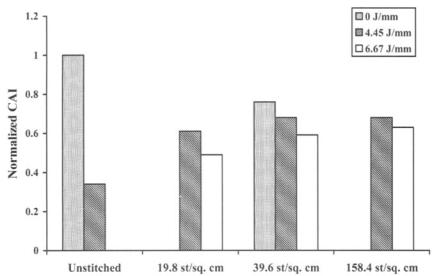
resulting from stitching is the increase in the interlaminar delamination resistance of FRP laminates under mode I and, to a lesser degree, mode II loadings. To achieve this, the stitches need to remain intact for a short distance behind the crack front and restrict any effort to extend the delamination crack. As expected (with the enhanced fracture toughness), stitched FRP composites have a better resistance to delamination cracking under low energy, high energy, and ballistic impacts as well as under dynamic loading by explosive blasts. They also possess higher post-impact residual mechanical properties than do their unstitched counterparts, 1 as illustrated in Figure 14.3. It has been shown that the
( |
Needle |
|
~ . . . . P r e s s e r foot |
( |
Preform |
~ ' " ~ " - - - ~ |
Roller mechanism |
Fig. 14.1 Schematic diagram of the stitching configuration.
494 COMPOSITE MATERIALS FOR AIRCRAFT STRUCTURES
NIN~Ie
|
|
|
B o b b i n |
|
|
|
T h r ~ d |
a) |
|
|
|
|
P t |
~ |
N m a ~ |
JC |
If¸ If. . . . |
T h r e ~ |
|
|
|
Bobbin |
h)
c)
Fig. 14.2 Schematic diagrams of three commonly used stitches for z-reinforcement of two-dimensional composites: a) lock stitch; b) modified lock stitch; c) chain stitch.
effectiveness of stitching for improving residual strength is dependent on factors such as the stitch density, stitch type, and stitch thread. However, only in relatively thick laminates are significant improvements in compression-after- impact strength evident. Although it is noted that a toughened matrix could also provide similar improvement in residual strength2 (Fig. 14.4), it is two or three times more expensive than stitching.
There have been, however, conflicting results that report that stitching does little (if anything) to improve either impact damage resistance or tolerance. In the cases considered, this is normally attributed to two factors: 1) the stitching yarns were insufficiently strong (both in terms of breaking strength and providing traction) to afford the necessary resistance to delamination growth; and 2) the bridging zone (of between 2 0 - 3 0 mm) needed for stitches to be effective, was not fully realized.
Undisputed, however, is the advantage of stitching for improved shear lap joint strength under both static and cyclic loading, largely due to reduced peel stresses. Stitches can delay the initiation of disbonds and provide load transfer even after failure of the bond line. Therefore, stiffeners stitched onto a panel are
496 COMPOSITEMATERIALSFORAIRCRAFTSTRUCTURES
70 0
. /
60 0
t~
0 .
=E
~500
c
=400
t,O e-
0 30O
i
.o
unstitc~d " ed
~" 200
E
o o
100
0 |
20 |
40 |
60 |
80 |
100 |
|
|
I m p a c t |
Energ y |
J |
|
Fig. 14.4 NASA results for compression after impact for 48-ply quasi isotropie AS4/3506 laminates, either stitched or unstitched, and an unstitched laminate of similar configuration with a highly toughened matrix. Stitch pitch and spacing around 3 mm . Based on data provided in Ref. 2.
delaminations. The stiffness in tension and compression is mainly degraded when in-plane fibers are misaligned by the presence of the stitching yam in their path.
Premature compressive failure can be triggered if stitches are too taut, which in turn can cause excessive crimping of the in-plane fibers. Conversely, insufficient tension of the stitching yam can cause the stitches to buckle under consolidation pressures and render them ineffective as a reinforcement in the thickness direction, the purpose for which they were originally intended. Tensile strength, on the other hand, is normally degraded due to fiber fractures arising from damage by the stitching needle. Enhancement of tensile strength, which has been observed, is attributed to an increase in fiber/volume fraction resulting from compaction of in-plane fibers by the stitching.
It is also considered that the inferior fatigue performance observed for stitched composites under tension and compression loadings is due to the same failure mechanisms that are responsible for deterioration in their corresponding static properties.
Finally, it appears that the flexural and interlaminar shear strengths of twodimensional laminates may also be degraded, unchanged, or even improved with stitching. In general, the conflicting effects of stitching, in increasing fiber content and suppressing delamination, on the one hand, and introducing
THREE-DIMENSIONALLY REINFORCED PREFORMS |
497 |
misalignment and damage to in-plane fibers, on the other, are possibly responsible for the reported behaviors.
14.2.2 Applications of Stitching: The Stitched Wing
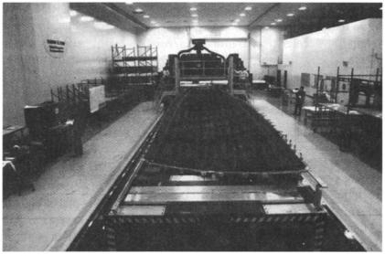
To date, by far the most ambitious development of stitched composite structures is a NASA sponsored demonstrator program to develop a cost-effective damage-tolerant composite wing. A 28-m-long sewing machine,4 shown in Figure 14.5 was developed by Boeing to manufacture preforms with enhanced impact tolerance for the production of composite aircraft wing covers. The machine is able to stitch layers of carbon fabric of over 25 mm in thickness at a rate of over 3000 stitches a minute. In addition to stitching the skin preform, the blade stiffener flanges are also stitched to the skin. The stiffeners are formed by stacking tubular braided fabrics and partially stitching them together, leaving an unstitched region that is folded out to form the flanges before they are stitched to the skin.
After stitching, the flexible wing preform is placed on an outer mold-line tool pre-covered by film of partially cured resin; thereafter, the assembly is bagged and placed in an autoclave. Under heat and pressure, the resin melts and flows through the skin and stiffeners before curing. This process is known as resin film infusion (RFI) and is covered in Chapter 5. The resulting panel is claimed to be 25% lighter and 20% cheaper than an equivalent aluminum part.
Fig. 14.5 Boeing sewing machine for stitched wings.