140 COMPOSITE MATERIALS FOR AIRCRAFT STRUCTURES
R e c t i l i n e a r R T M Mold. The one-dimensional Darcy's law is:
|
|
a - |
KAdP |
|
|
(5.2) |
|
|
|
r / d x |
|
|
|||
|
|
|
|
|
|
||
where Q is the volume flow of resin per unit time. |
|
|
|||||
Assuming - ( d P / d x ) |
constant: |
|
|
|
|
|
|
Q = vA(1 - |
Vf) - |
K A P |
|
|
|
(5.3) |
|
~T x |
|
|
|
||||
|
|
|
|
|
|
|
|
average velocity: |
dx |
- |
K P |
1 |
|||
v - |
dt |
|
(5.4) |
||||
|
|
|
|
r/(1 - |
V f ) x |
||
Solve for time by integrating the equation (5.4), where |
|||||||
K is the permeability |
|
|
|
|
|
|
|
P is the injection pressure |
|
|
|
|
|
|
|
Vf is the fiber/volume fraction |
|
|
|
|
|
||
x is the mold length |
|
|
|
|
|
|
|
~7 is the resin viscosity |
|
|
|
|
|
|
|
t is the time to fill |
|
|
|
|
|
|
|
A is the mold cross-sectional area (width |
x |
thickness) |
|||||
Answer: t - r/(1 - |
V f ) x 2 _ |
0.4(1 - |
0.54) |
(0'2)2 = 526 seconds |
|||
K P |
2 |
3.5E -11 x 200,000 |
|
2 |
|||
5.5Filament Winding
5.5.1General
Filament winding 9'1° is a composite-material manufacturing process that enables continuous reinforcement to be laid down at high speed and precision in predefined (generally, geodesic) paths. The process basically involves the winding of continuous fiber, impregnated with resin, over a rotating or stationary mandrel. The mandrel, whose geometry cannot include any re-entrant curvature, is subsequently removed after cure. By varying process parameters, such as winding tension, winding angle, and resin content, during the laying of the fiber, the desired part thickness, ply lay-up, and fiber/volume fraction can be achieved.
Filament winding is considered to be less versatile than other composite manufacturing techniques, particularly for complex shapes with varying thickness and fiber orientation. The process is better suited to parts with simple surfaces of revolution, although developments of the process with the introduction of multiaxis machines and sophisticated control software has enabled more complexshaped components that are non-axisymmetric to be produced.
COMPONENT FORM AND MANUFACTURE |
141 |
5.5.2Winding Process
The basic filament-winding machine (Fig. 5.19) comprises a mandrel, fiber feed head and carriage, drive systems, and control box. The mandrel is motor driven such that it rotates about its longitudinal axis. As it rotates, it takes up fiber from the feed head. The feed head is attached to a carriage that is located onto a track, enabling the head to traverse back and forth in a direction parallel to the longitudinal axis of the mandrel. The speeds at which the mandrel rotates and the feed carriage traverses determine the orientation of the fiber being laid down. Basic winding machines can be programmed simply by changing the gearing between the mandrel and feed carriage. Ancillary devices are also used to maintain tension in the fiber as it is being taken off supply spools or creels. The tension in the fiber controls the level of compaction in the wound part.
In the wet-winding procedure, the fibers pass through a heated resin bath before reaching the feed head and are then deposited onto the mandrel. In this situation, rollers are used to remove excess resin, to force remaining resin into the fibers and flatten the tows. A variation to this is the controlled wet procedure, in which resin is metered onto the fiber. In the case of pre-preg winding, the resin bath and rollers are not required, the pre-impregnated fiber being fed directly into
Fig. 5.19 Filament winding machine. Courtesy McClean-Anderson, Schofield, Wisconsin.
142 COMPOSITE MATERIALS FOR AIRCRAFT STRUCTURES
the feed head from the spools, then laid onto the mandrel. For pre-preg winding, the mandrel is generally heated to promote resin tack and flow. The fully wound part is then cured either at room temperature in an oven or in an autoclave, depending on the resin system.
The design of the mandrels used in filament winding is highly dependent on the winding machine capabilities, the structural requirements of the part, and the processing characteristics. Mandrels are generally constructed of steel or aluminum, and for situations in which the mandrel forms part of the structure or simple extraction of the mandrel is possible, the mandrel is in one piece. Where simple withdrawal is not possible, various types of removable mandrels are required. This may involve segmented metal mandrels, or mandrels constructed of materials that are soluble, fusible, inflatable, or collapsible.
5.5.3Winding Patterns
There is a range of winding patterns used in filament winding, with the three primary classes being hoop, helical, and polar (See Fig. 5.20). The simplest is hoop winding, which comprises a mandrel rotating continuously about its longitudinal axis while the fiber feed carriage advances one fiber bandwidth after each mandrel axis of rotation. Consequently, fibers are deposited almost normal to the longitudinal axis. Helical winding, which is most commonly used, is achieved when the mandrel rotates continuously about a horizontal axis while the fiber feed carriage traverses back and forth. Winding angles ranging between 2 5 - 8 0 ° can be achieved with this method. In polar winding, the mandrel is rotated perpendicular to its longitudinal axis and remains stationary while the fiber feed arm rotates about the longitudinal axis, inclined at a slight angle. After each revolution of the feed arm, the mandrel is indexed to rotate about its longitudinal axis by one fiber bandwidth. A variation to polar winding is whirling winding, whereby the mandrel is rotated about a vertical longitudinal axis.
The basic winding patterns enable continuous fiber to be laid down onto the mandrel in the hoop, longitudinal, and bias directions. The ability to achieve these pattems is dependent on the type of filament winder being used. Basic filament winding machines have only two axes, thus limiting the pattems and shapes that can be wound. More sophisticated machines, such as robotic CNC filament winders, can have up to 10 axes of movement, which enables a greater range of patterns and more complex-shaped parts to be wound. These CNC machines have computerized servo-controls that allow complex winding procedures to be defined before their automatic execution.
5.5.4Materials
The fibers used in the filament winding process typically come in two forms. Wet winding uses dry fibers that are impregnated with a low-viscosity resin during the winding process. In some cases, the part may be wound entirely with
COMPONENT FORM AND MANUFACTURE |
143 |
Whiding
Polar
Hoop |
Helical |
Fig. 5.20 Schematic diagram of the various filament winding machines and patterns. Adapted from Reference 18.
dry fiber then impregnated with resin under pressure. Pre-preg winding utilizes fibers that have been encapsulated within a B-staged resin. The advantages of wet winding are that it uses materials in the lowest cost form having no shelf life limits, and also that it requires fewer compaction cycles during the winding process. Pre-preg systems, on the other hand, can produce parts with higher quality and consistency, reduce winding times, minimize the chance of fiber slippage, and require less consolidating after winding.
Thermosetting resins are most commonly used in filament winding, where consolidation of the material takes place after the winding has been completed. More recently, thermoplastic resins have been used in the form of pre-preg and consolidation takes place as the material is being laid down.
144 COMPOSITE MATERIALS FOR AIRCRAFT STRUCTURES
Further discussion of filament winding of thermoplastic composites appears later in this chapter.
5.5.5 Design and Properties
The analysis of filament-wound structures is usually carried out using a netting approximation. This assumes that the fibers are uniformly loaded in tension and provide all the longitudinal stiffness and strength while the resin provides only the shear stiffness. This is a conservative approach; a more realistic procedure is to use techniques such as composite laminate theory (See Chapter 6).
The properties of filament-wound structures are generally inferior to composites made by conventional methods. This can be attributed to the higher void contents that can be as high as 7% for wet-wound material. If the fiber tension is too high, air will be entrapped at crossover points and within the tows that are unable to spread. If the resin viscosity is too high, the entrapped air is also unable to escape. To some extent, excessive voiding may be reduced by control of fiber tension and use of low-viscosity resins, however, autoclave processing with prior vacuum treatment is a more effective method of minimizing voids.
The winding pattern can also contribute to variations in the mechanical properties. Helical winding patterns produce fiber tow crossovers that result in crimping of the fiber and increase stress concentrations at these points. However, interweaving does result in improved interlaminar performance.
One of the most significant problems occurring in filament-wound structures is layer or fiber waviness, which can result in a significant loss of strength and stiffness. The waviness is mainly caused by volumetric changes during resin bleed-out in thick wound structures. It can therefore be avoided by minimizing the amount of resin that needs to be removed and maintaining the correct level filament tension during winding.
5.5.6 Applications
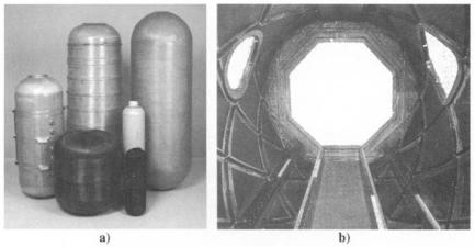
The advantages of the filament winding process are best exploited on components with simple surfaces of revolution. Examples of aerospace parts that have been fabricated using filament winding include rocket-motor cases, pressure vessels, missile launch tubes, and drive shafts. Some of these components, especially rocket-motor cases, can be very large (exceeding 4 m in diameter). Metal end-closures and metal or rubber internal liners are commonly incorporated into the design of filament-wound pressure vessels. These additions are placed onto the mandrel before winding. Filament winding is also commonly used for non-aerospace applications, such as storage and processing tanks, reinforced pipe, crane booms, automotive drive shafts, springs, golf shafts, fishing rods, and paddle shafts.
Filament winding has also been shown to be an ideal method for making geodesic composite structures. These structures utilize reinforcement in an
146 COMPOSITE MATERIALS FOR AIRCRAFT STRUCTURES
Resin impregnation and fiber guiding
I
Creel Fibers |
1 |
|
|
|
|
1 |
Controls |
|
Cut-off saw |
||
|
/ |
o,. / |
..o,oronoou,,.o\ |
||
|
|
|
Profile |
~ |
Take-off |
Fig. 5.22 Schematic diagram of basic pultrusion machine (Reference 11).
system being used and the die length. Dies are typically 1 m long and pulling speeds vary between 200 m m min -1 for epoxy-based products to 3000 m m m i n - 1 for commercial, polyester-based products. With epoxy-based systems, full cure is not normally achieved before the part exits the die, and post-curing operations need to be considered (either onor off-line).
5.6.1Reinforcements
Almost all reinforcement material and forms can be processed by the pultrusion technique, including glass, aramid, polyethene (polyethylene), and carbon fibers. One intrinsic requirement of the process is the need for a high percentage of fibers aligned parallel to the pulling direction. With need for off-axis fibers, as is the case for aerospace products, there is a fundamental requirement to have sufficient zero degree fibers to withstand the pulling forces required to draw the array of collimated fibers and fabrics through the die. When off-axis reinforcement is required, such as at 90 ° or + 45 °, stitched non-crimp fabrics (NCF) can be used. However, these fabrics are effectively incompressible and can give rise to rapid pressure rise at the die entrance.
5.6.2Resins
With transient times of typically 0.5 - 5 . 0 minutes in the heated section of the die, it is essential to use a resin system that gels and/or cures very rapidly.
The majority of commercial pultrusions are manufactured with polyester resin. This is because it is inexpensive and is the easiest resin to process. In applications in which the fire resistance is of primary Importance, phenolic resin is normally selected. However, there are certain considerations that must be taken into account when pultruding phenolic-based products. First, the compatibility of the phenolic resin with conventional sizing on glass fibers is poor, and second, in
COMPONENT FORM AND MANUFACTURE |
147 |
some systems? water, in the form of steam, is generated as a by-product of the curing reaction. Without careful management, the water can remain trapped in the product, resulting in a severely voided laminate. The mechanical properties of phenolic laminates are typically lower than those having polyester or vinyl ester resin systems, and the production rates are also slower.
Epoxy resins are selected for applications where the mechanical properties need to be maximized, such as in aggressive environments and military or aerospace applications. However, epoxies are notoriously difficult to process by pultrnsion because the curing mechanism of epoxies is significantly different to that of polyesters and vinyl esters. Epoxies cure very slowly and take a long time to reach their gel point; it may not occur until just before the die exit. Also, the degree of cure at the die exit may be as low as 70 - 80% .
To maximize the transient time, pulling speeds are normally very low when processing epoxy-based products. Epoxies also have very low cure shrinkages and are exceptional adhesives, which in combination can lead to a surfaceroughening phenomenon called micro-sloughing.
5.6.3 Pultrusion Process
The process can be separated into three key stages:
•Fiber in-feed system--includes fiber-dispensing, impregnation, collimation, and forming
•Forming system--includes external heating, die design, and the curing
reaction
• Pulling system includes pulling mechanism and the cut-off station
5.6.4 In-Feed System
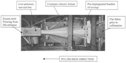
Of the three stages listed above, the in-feed system, an example of which is shown in Figure 5.23, is by far the most important to the smooth and successful operation of the pultrusion process.
The reinforcing fibers are usually used in a combination of rovings and broadgoods. The rovings are traditionally stored on multi-layer racks called creels, and the fabric is slit to the required widths and dispensed from rolls. The fibers and fabrics can be impregnated with resin either collectively, toward the end of the forming process, or individually at intermediate stations, located throughout the in-feed system. Once impregnated, and before final collimation, the fabrics pass through a series of shaped formers that squeeze-off excess resin. This stage also encourages thorough infiltration of the resin and wet-out of all fibers.
5.6.5 Tooling System
The tooling system consists of a pair of closed, matched dies that are about i m in length. The die cavity forms the shape of the finished part and, apart from