COMPONENT FORM AND MANUFACTURE |
149 |
fiber optic cable core, which is 0.002 m diameter and wound onto a spool mounted at the end of the pultrusion machine.
5.6.7 Aerospace Applications
Start 11 gives a comprehensive overview of the ever-increasing number of applications of pultrusion from cable-trays and window lineals to full-scale bridge decks and railway bridge constructions.
Within the aerospace market, however, successful examples of the use of structural pultrusions are relatively few. This is due primarily to the limited production runs required for aerospace products; demands are usually too short for the pultrusion process to be viable. Production runs of aircraft are usually measured in hundreds, spread over several years. It is also due in part to the difficulty in reaching the quality of product achievable with other aircraft-molding techniques. This arises both from the unsuitability of most high-performance resins and the difficulty of achieving high-volume fractions when using off-axis reinforcement. Nevertheless, through the development of special resins, high-performance aerospace quality pultrusions with relatively high Vf have been produced, an example of which is shown in Figure 5.24.
5.7Process Modelling
One of the main barriers to more widespread application of advanced composite structures is their relatively high cost compared with parts made of
Fig. 5.24 Prototype, structural I-beam, produced using carbon fiber tows and NCFs with an epoxy resin system. Courtesy of CRC-ACS Ltd, Australia.
150 COMPOSITE MATERIALS FOR AIRCRAFT STRUCTURES
conventional aluminum alloys. The high cost of composite manufacturing is partly due to the trial-and-error philosophies adopted in the manufacturing tooling design and process development. It is therefore very desirable to be able to predict the material and tooling responses during manufacturing through the use of process modelling or simulation. Process modelling may help to reduce the manufacturing cost and time on two different scales. First, it is possible to optimize the tooling and process design for a manufacturing process through process modelling if the fundamental response of the materials involved can be characterized relatively accurately. Second, and more broadly, process modelling can be used to predict a desired tooling and process design window within which a reduced number of trials can be conducted.
The processing of advanced composites involves a number of coupled physical and chemical phenomena. These include heat and mass transfer in the two-phase media (reinforcement and matrix), resin cure reactions, and deformation caused by temperature changes, resin cure shrinkage, and applied forces. These phenomena are governed by the well-known conservation rules, such as conservation of energy, conservation of resin mass, and conservation of momentum. Process modelling is used to solve the relevant governing equations under a set of given initial and/or boundary conditions to predict the process variables such as temperature, degree of cure, pressure, flow front positions, and deformation of composite part and tooling. Due to the general complexity of both the process and the part geometry, an analytical solution is usually not possible and therefore a numerical method, such as the finite difference method or the finite element method, has to be used.
5. 7.1 Forming of Reinforcement Stacks
Forming a stack of reinforcement layers, whether they be pre-preg plies or "dry" fabric plies for use in RTM, involves transforming a fiat stack of reinforcement into a three-dimensional shape. However, the deformation behavior of pre-preg is more complicated than that of the dry reinforcement, making it much more difficult to model.
Two approaches are commonly used to model forming: the kinematic mapping approach and the mechanics approach.
In the mapping or kinematic approach, forming is considered purely as a process of geometrical transformation: the initially fiat sheet of material is mapped onto the three-dimensional surface of the forming tool. The material is assumed to be inextensible in the fiber direction and the draping is achieved through shear deformation. Any forces required to shear the fabric are ignored. Consequently, the mapping approach provides only geometrical or strain information on forming, such as fiber orientation in the formed part and the total shear strain experienced by the part. The mapping approach is a
good initial tool for investigating forming |
requirements, and may be all that |
is required for predicting the formed shape |
in hand lay-up of single layers of |
COMPONENT FORM AND MANUFACTURE |
151 |
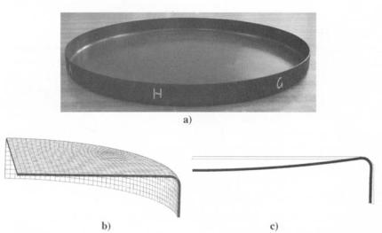
pre-preg or dry fabrics, or preforming of stacks of dry fabric layers with the same orientation. Figure 5.25 shows fiber paths in a woven fabric draped over an aircraft rib shape, predicted by the software Drape from the Technical University of Delft.
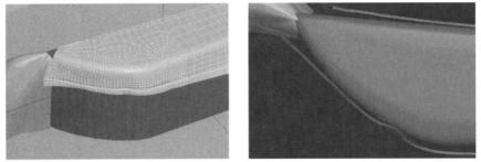
The mechanics approach solves equilibrium equations balancing the forces within the material against the applied loads, and the constitutive equations describing how the stress in the material is related to strain and/or strain rate. The transient forming process is modelled by time stepping. Such a model is usually complicated due to the complex deformation modes of composite sheets. It has to be solved by the finite element method and requires large computing power. However, a mechanics model can provide not only more detailed geometrical information, but also the transient strain and stress states in the material, which is needed to predict forming defects. Therefore, much recent development in the modelling of composite sheet forming has used this approach. Figure 5.26 shows the predicted forming behavior of a cross-plied stack of woven pre-preg formed over the same rib shape. The software used is PAMFORM from Engineering Systems International.
Fig. 5.25 Kinematic draping predictions for different fabric orientations.
152 COMPOSITE MATERIALS FOR AIRCRAFT STRUCTURES
Fig. 5.26 PAM FORM predictions for forming a ply stack over a rib shape.
5. 7.2 Heat Transfer and Resin Cure
Advanced composites are usually cured at the relatively high temperature of about 180°C. During a composite curing process, heat transfer and cure in composites are governed by the following equations:
__ OT |
|
( |
OT |
OT |
|
Uz--OT) |
|
|
pCp ~ |
|
qtwrorCpr UX~x -[- tlY--~"[- |
OZ |
|
||||
|
|
_ 0 2 T |
_ |
0 2 T |
aZT |
|
|
|
|
= Kx~Ox |
~- Ky~y2 + kz ~ |
+ VrPrnrRr |
(5.5) |
||||
Ool |
|
Oa |
Ool |
|
Oa |
|
|
|
O~-~- ux OX ~ Uy~y ~ Uz ~Z = Rr |
|
|
(5.6) |
|||||
where ~ and ~p, respectively, are density and specific heat of the composites; kx, ky and kz are the directional thermal conductivity of the composites; Pr, Cpr, and Kr, respectively, are density, specific heat, and conductivity of the resin; Vr is the resin volume fraction; Ux, Uy, and uz are the components of resin flow velocity; Hr and R r are the total heat of reaction and the rate of reaction of the resin, respectively; and c~ is the degree of cure.
For a thermoset resin, the rate of reaction (Rr) at various temperatures can be experimentally determined by differential scanning calorimetry (DSC). The results are then fitted to an equation expressing Rr as a function of temperature T and a. The following Arrhenius-type equation is most frequently used:
Rr - - dt - K0exp - am(1 - cOn (5.7)
where R is the universal gas constant, Ko, E, m, and n are the parameters to be determined by the fitting.
The existence of resin flow velocity (ux, uy, Uz) in equations (5.1) and (5.2) means that modelling of heat transfer and cure in composites is normally coupled
COMPONENT FORM AND MANUFACTURE |
153 |
with simulation of resin flow. This is often referred to as non-isothermal flow simulation. However, some manufacturing processes, such as autoclave curing and the curing stage of RTM, involve insignificant resin flow. For these processes, the above equations can be simplified by setting the relevant velocity components to zero and can be solved to predict the temperature and curing profiles.
Pultrusion is considered as a special case for which the resin flow relative to the reinforcement can be ignored and hence a coupling with flow simulation is also not needed. However, heat transfer and cure modelling for pultrusion is still somewhat complicated owing to the constant movement of the pultruded part in the pulling direction. The governing equations for a pultrusion process can be written as follows:
OT |
uOT"] |
_ 02T |
02T _ 02T |
(5.8) |
~ p ~ |
"~- OX/] = |
Kx~x2 -~- Ky--~'Jv Kz~z2 "~- VrPrnrgr |
||
|
|
Oa |
Oa |
(5.9) |
|
|
~ "t- U-~X = g r |
||
where u is the pulling speed.
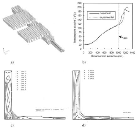
The above equations can be solved using the finite difference or the finite element method to predict the temperature and curing profiles in pultrusion. Figure 5.27 shows the temperature and curing profiles at the die exit for the pultrusion of a fiberglass-vinyl ester composite I beam, predicted by using the finite element method. Owing to the symmetry in the die, only one quarter of the section need be modelled.
5. 7.3 Resin Flow Through Fiber Reinforcement
The flow of resin through fiber reinforcement is considered to obey Darcy' s law that states that the velocity of the flow is proportional to the pressure gradient in the resin. Combined with the assumption of resin incompressibility, one can derive the following resin pressure equation:
Ox \ t~ Ox,I + Oy \ ~ -@] + Oz \-~ -~z,I = 0 |
(5.10) |
where Sx, Sy, and Sz are the directional permeability of the reinforcement and/.~ is the viscosity of the resin.
The above equation can be solved analytically for the simple cases of isothermal, one-dimensional flow and isothermal radial flow. The solutions have been used to process results of tests to determine the permeability of reinforcement.
To solve these equations for any more complex case, the finite element/ control volume method is most frequently used. In this method, the reinforcement is divided into elements/control volumes. A fill factor between 0 and 1 is assigned to each of the control volumes, with 0 indicating an empty volume and 1 for a

156 COMPOSITE MATERIALS FOR AIRCRAFT STRUCTURES
where my is the coefficient of volume change, which can be related to the fiber/ volume fraction and the fiber compaction stress as follows:
1 |
dVf |
my -- |
(5.13) |
Vfd p
The relationship between Vf and p needs to be determined by a compaction test. It is also necessary to experimentally determine the permeability as a function of the fiber/volume fraction. It has been shown that the results of the permeability test can be fitted to the Kozeny-Carman equation:
S -- r} |
(1 - Vf)3 |
(5.14) |
4Kz |
V~ |
|
where ryis the fiber radius and Kz the Kozeny constant.
Consolidation modelling has been used for some time to simulate autoclave consolidation of thick pre-preg composites in which the resin flow is predominantly one-dimentional in the thickness direction. More recently, it has been used in other situations such as the simulation of compression RTM and of vacuum bag resin infusion.
5. 7.5 Process-Induced Distortion and Residual Stress
Five main factors have been identified as responsible for process-induced part distortion and residual stress in composite structures. These are thermal strains, resin cure shrinkage strains, gradients in temperature and resin degree
of cure, resin pressure gradients, and tooling mechanical constraints. To fully |
|
model the development of the part distortion and residual stress during a |
|
manufacturing process, it is necessary to include the transient |
temperature, |
resin flow and cure, and the tooling and part deformation |
under load. |
Therefore, modelling |
of process-induced part distortion and residual stress |
is one of the most |
complex process modelling tasks, requiring modelling |
of heat transfer and |
cure, flow simulation, and consolidation analysis as |
sub-models. |
|
Fortunately, aerospace composite structures are often thin panels cured in an autoclave or oven. For these panels, it is reasonable to assume that the gradients in temperature and resin degree of cure are small and can be ignored. Furthermore, the majority of resin cure shrinkage may occur very early in the curing process, when the resin behaves as a viscous fluid or is at least highly viscoelastic. Therefore, the cure shrinkage strains will be relaxed in the subsequent curing and contribute little to the final part distortion. This suggests that the thermal strains caused by the thermal mismatch between different directions/different plies are often the only major source of residual stress. Consequently, prediction of the process-induced distortion and residual stress can often be simplified to a structural analysis of the composite panel loaded