

436 COMPOSITE MATERIALS FOR AIRCRAFT STRUCTURES
In the 1960s the development of S2-type glass, which has greater stiffness and strength than E-glass, allowed a greater variety of aircraft structures and components to be made. S-glass composites are often used as the face skins to ultra-light sandwich honeycomb panels, and typical applications in commercial aircraft are wing-fuselage fairings, redder and elevator surfaces, and the leading and trailing edges of wing panels. Glass/epoxy honeycomb sandwich panels are also used in a variety of components on modem military aircraft, such as the fixed trailing edge on the B-2 bomber. Another common use of composites with E-glass or quartz fiber reinforcement is in radomes on commercial and fighter aircraft, in bayand wing-mounted radomes on supersonic aircraft and missiles, and in the large radar domes on Airborne Early Warning and Control (AEW&C) military aircraft. This is because of the excellent transparency of glass to radar signals. Glass/epoxy is widely used in helicopter components, such as in the spars to the main and tail rotor blades, fuselage body panels, and flooring. Glass fibers are also used in combination with carbon and Kevlar fibers in hybrid composites for a wide variety of aircraft components, such as wing-body fairings, engine pylon fairings, and engine cowlings. Polyesters have been used in composites for cabin interiors; however, in this application, phenolics are now preferred due to their excellent flame resistance.
12.3Current Applications
12.3.1Fixed Wing Civil Applications
As mentioned in Chapter 1, the adoption of composite materials for aircraft structures has been slower than originally foreseen, despite the weight-saving and corrosion and fatigue immunity offered by these materials. The reasons for the restrained use include the high cost of certification and higher materials and production costs for composite components. Composite structures must not be significantly more costly to acquire3 than those made of aluminum alloy and, to maintain the advantage of weight saving, maintenance costs also, must not be greater.
Sensitivity to impact damage and low through-thickness strength are also inhibiting factors. Other issues are the poor reliability in estimating development costs and difficulty in accurately predicting structural failure.4
Although a few inroads have been made in terms of reducing certification costs, recently there has been the development of more cost-efficient manufacturing methods, such as resin-transfer molding and pultrusion, and improved resin and fiber systems that provide increased toughness are making composites very strong candidates for new designs. Another important benefit is the reduction of airframe assembly costs, as composites lend themselves to the manufacture of large unitized structures.
After some years of stagnation, the use of composite materials in large aircraft structures has increased over the past half-decade as manufacturers take
AIRCRAFT APPLICATIONS AND DESIGN ISSUES |
439 |
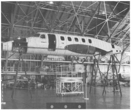
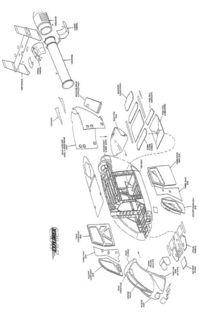
Fig. 12.3 Premier 1 composite fuselage. Courtesy of the Raytheon Corporation.
mostly made of carbon/epoxy, with honeycomb skins and internal structure. The fuselage makes extensive use of composites. However, this form of construction is very costly and more recently, affordability is considered to be as important as performance and is now a major design parameter.
The need for high stiffness to minimize the depth of wings and tail in highperformance military aircraft both for aeroelasfic and stealth reasons ensures that all future aircraft will have composite wing and empennage skins. The requirement for stealth as well as minimum weight also ensures that most of the fuselage skin will be composite. For radar absorption, leading edges will be made of honeycomb structure with outer composite skins based on nonconducting fibers such as quartz rather than carbon in the rest of the structure. This skin material allows the radar waves to penetrate into the honeycomb core coated with radar-absorbing material, rather than being reflected back to the receiver.
Despite the structural advantages of honeycomb construction, there is a trend to replace this form of construction with stiffened cocured composite panels, because these are much less prone to damage and to water entrapment. Honeycomb is still used in some regions for stealthy structure as discussed previously and where structurally advantageous, for example, in control surfaces.
440 COMPOSITE MATERIALS FOR AIRCRAFT STRUCTURES
Some military aircraft such as the Harrier, have much o f the internal structure o f the wing made o f carbon fiber reinforced plastic composite, in addition to wing skins, some in the form o f sine wave spars (see Figure 12.4). However, in more recent fighter aircraft there is a trend back to metals for much o f the wing substructure. This is because o f the relatively high cost o f composite substructure, compared to high-speed machined aluminum and the limited tolerance o f composites to ballistic impact. Often titanium alloy is used for the main loadbearing spar because o f its superior resistance to ballistic impact and its excellent fatigue properties.
The airframe o f the F-22, as an example, 4 is made o f 39% Ti 64 titanium, 16% aluminum alloy, 6% steel, 24% thermoset composite - carbon/epox y and c a r b o n / B M I and 1% thermoplastic. The structure is given as follows.
• Forward Fuselage:
- skins and chine - composite laminates
-bulkhead/frames resin transfer moulded composite and aluminium
-fuel tank frames and wallsRTM composite
- |
side array doors and avionics - formed thermoplastic |
• Mid Fuselage: |
|
- |
skins - composite and titanium |
- |
bulkhead and frames - titanium aluminum and composite |
-weapon-bay doors -skin thermoplastic, hat stiffeners, R T M composite
•Aft Fuselage:
-f o r w a r d boom - welded titanium
-bulkhead and framestitanium
-keel web-composite
•Wings:
-skins composite
- spars - front titanium, intermediate and rear- R T M composite and titanium
-side o f body fitting HI P cast titanium
•Empennage:
-skin composite
-core - aluminium
-spars and ribs-RTM composite
•Duct Skins:
-Composite
•Landing Gear
-steel
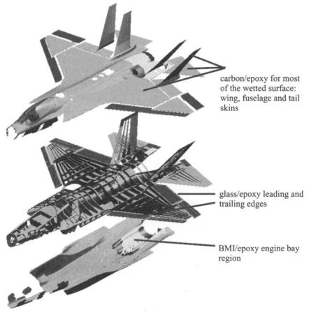
Some general details o f the construction o f some current fighter are provided in Figure 1.2 for the F / 1 8 E F and in Figure 12.5 for the Joint Strike Fighter. In the JSF extensive use was planned (at the time o f writing) o f the lightweight aluminum lithium alloy for the wing and other substructure.
AIRCRAFT APPLICATIONS AND DESIGN ISSUES |
443 |
12.3.3 Rotorcraft Applications
The early applications for composite materials in helicopters were in rotor blades and drive shafts. The attraction for rotor blades is the ability to produce complex aerofoil shapes and high-quality surface contours using simple construction methods. Fiberglass has often been used because the stiffness of the blades is not usually a design problem, the predominant load being tension caused by centrifugal forces. Use of composites in drive shafts is attractive but the opposite reason applies and here, torsional stiffness is an imperative and carbon fiber reinforced plastic composites offer a significant weight saving. Filament winding is an attractive manufacturing process for these components particularly for drive shafts where there is a need for ply orientations at + / - 45 ° for maximum torsional efficiency.
Composite materials are now used for flex-beams in the design of 'bearingless rotor hubs' that are now becoming universally adopted. Composites allow flexural stiffnesses to be tailored into the otherwise rigid beam allowing the necessary blade flapping action arising from forward flight. Pitch cases, that transmit the pitch angle to the blade, have similar requirements to drive shafts and are also being constructed from carbon fiber reinforced plastic composite.
Over recent years, the use of carbon fiber shell structures for fuselages and tailbooms has also been spreading. The MD Explorer employs carbon fiber reinforced plastic composite for almost 100% of the non-transparent external structure (see Figure 12.6). The US ACAPS helicopter crashworthiness assessment program run in the 1980s showed the advantages of using composites in the tub structures for energy absorption under crash-landing conditions. Composite structures when designed properly have a significantly better specific energy absorbing capacity than aluminum alloy structures under crushing conditions.
The V-22 tiltrotor is an excellent example of the beneficial use of carbon/ epoxy composite construction.4 Use of composites is credited with saving 13% structural weight and reducing costs by 22%. However, to save cost, even in this highly weight-sensitive application, some of the internal fuselage structure, originally planned to be made of composite, is now made of aluminum alloy.
12.3.4Common Configurations
Table 5.1 lists the various types of composite construction used in aircraft structure. Early composite designs tended to be of sandwich construction, featuring honeycomb cores. This construction is highly efficient structurally and, provided the core is relatively shallow, also quite cheap to manufacture. Unfortunately there have been many examples of disbonding in service. This problem in honeycomb structure is common to both metallicand compositeskinned construction and mostly results from the ingress of moisture into the core
AIRCRAFT APPLICATIONS AND DESIGN ISSUES |
445 |
through poorly sealed ends during ground-to-air pressure changes. It can also be a problem with thin composite skins, which can allow moisture to penetrate through microcracks. However, transport of moisture through the composite skins by diffusion does not seem to be a problem. Moisture penetration is particularly serious when the core is made of aluminum alloy because corrosion and bond separation result. Ingress of moisture can also cause de-bonding of the skins caused by expansion of entrapped moisture on freezing when operating at altitude.
A good design practice with honeycomb panels is to envelop the sandwich in a thermoplastic film such as Tedlar, which acts as a moisture barrier, that can be cobonded with the laminate. Cuts and darts in this film should be avoided, otherwise moisture can penetrate to the composite surfaces where it can then be absorbed into the substrate. Skin thicknesses should also not be less than 0.6 m m for the same reason. The use of an appropriate sealant must be applied to all cut edges.
Honeycomb-sandwich structures are also more prone to impact damage, and for these reasons, although accepted for secondary structures, some aircraft companies will not sanction the use of sandwich construction in primary structures. Closed-cell rigid foam cores are possible substitutes; however, the low melting temperature of PVC foams restrict its use to lower-temperature-curing (and hence lower-performing) systems. Higher-temperature-curing foams such as PEI may overcome this problem; however, some observations of the material cracking under cyclic strains have been reported, and care must be taken to ensure that the foam is completely dried before processing.
The alternative is a stiffened monolithic construction, and here the main issue is the means of attachment of the stiffeners. Some alternatives for attaching stiffeners are shown in Figure 12.7.
Although honeycomb construction is generally lighter than stiffened structure, this situation is reversed if the structure is allowed to buckle at limit-load. Compared with unbuckled stiffened structure, honeycomb saves approximately 20% weight, but post-buckled structure5 can save approximately 30%.
From a structural point of view, the integral cocured design is the most effective solution, particularly if the stiffeners must endure buckling of the skins without disbonding; however, lay-up costs are higher. To some extent, this cost may be offset by the reduction in parts count. With bonded discrete stiffeners (although cheaper to manufacture), care needs to be taken in matching the stiffness of the panel with the attaching flange, and avoiding excessive throughthickness stresses to avoid the possibility of peel failures. Thorough surface preparation is also essential to ensure a good bond.
Conventional mechanical fastening can be used with bonding as a conservative solution to improve through-thickness strength. Altematively, z-pinning (Chapter 14) is a novel method in which small-diameter composite pins are inserted through the thickness of the laminate for the same purpose.
446 COMPOSITE MATERIALS FOR AIRCRAFT STRUCTURES
Pr. .0 |
IIIIII |
/ Adhoslve~lm
a) ?
~" "Noodle"Filler
b) ;
c)
Fig. 12.7 a) Secondary bonded blade stiffener; b) cobonded blade stiffener; c) integrally cured blade stiffener.
A major NASA initiative in recent years has been to develop a cost-effective stitched stiffener wing plank using dry preforms and a resin film infusion process6 (see also Chapter 14).
The design of composite details has to be made with a clear view of the proposed assembly procedure. A major advantage of using composite materials is the possibility of reducing parts count by making very large components (and hence subsequent joining assembly costs and problems). "Single-shot" structures, such as has been achieved on the Boeing/NASA wing plank, in which components that would previously have been individually manufactured and assembled are molded in a single operation, are becoming the goal for many designers. Although this approach brings assembly savings, the additional complexities in NDI also needs to be considered.
Another key attraction of designing with composite materials is the opportunity to tailor the design through orientation of the fiber in the direction of the load. Although it is possible to optimize structural performance through fiber alignment and by providing ply buildups at load concentration points, the value of these