

158COMPOSITE MATERIALS FOR AIRCRAFT STRUCTURES
5.8Tooling
The fabrication of composite parts requires tooling that can be described as either closed-mold or open-mold. Closed-mold tooling is used for components produced by the RTM method, and these tools are matched with a cavity whose dimensions are controlled to achieve the specified fiber and resin volume fractions. These tools are usually made from steel due to the high pressures inside the mold required for injection and compaction. Pressure on the mold is usually achieved by a press, but for large parts an autoclave can be used. Small molds can be bolted together and are satisfactory provided that deflections can be minimized. Open-mold tooling is used for manufacture with pre-preg materials, RFI, or vacuum bag resin infusion (VBRI) and consists of a hard tool providing the shape of the required component (or outer mold line; OML) with compaction provided through a flexible bag or bladder. The tooling materials for open-mold tools can be metallic or non-metallic, the choice of which is largely driven by initial cost and the numbers of parts required from the tool. For large production runs, hard metals such as steel, nickel, or invar are preferred. Composite tools are lighter and can be produced by casting from a master shape. Although they are less durable, they can be easily repaired. Wood can also be used for materials with curing temperatures less than 100°C (these materials may require a post-cure that can be undertaken off the tool).
Other factors that need to be considered in the selection of tooling materials are dimensional stability, coefficient of thermal expansion, and specific heat.
Composite tools may be unstable at elevated temperatures if cross-linking has not been sufficiently completed during manufacture. Wooden tools will be unstable if not completely dried. The tendency for uptake of moisture by wooden tools requires they be sealed with an epoxy or similar gel coat.
Carbon fiber composites have very low coefficients of thermal expansion compared with steel and aluminum. Because the part will be cured into shape at an elevated temperature, allowance has to be made for the expansion of the tool at that temperature. Subsequent contraction of the composite part can then usually be neglected, however, care must be taken to ensure that the part does not lock or is cracked due to contraction of the tool on cool-down. This is a particular concern for closed-mold tools.
A high specific heat is desirable to improve the heat-up rate of the tool. This means less energy is required through the curing process and, additionally, cycle times can be reduced.
5.8.1 Metallic Tooling Materials
The most commonly used metallic materials are aluminum alloy, steel, electroformed nickel, and invar.
Aluminum alloy is attractive due to its relatively low cost, ease of machining, and low density. It also has a high specific heat. Unfortunately, because of the low
COMPONENT FORM AND MANUFACTURE |
159 |
hardness, aluminum tools are easily scratched and damaged. The high CTE (aluminum CTE is twice that of steel) requires considerable compensation be allowed for the dimensions of the tool. This is used to advantage, however, when aluminum is used for internal mandrels where the higher expansion acts to compact the composite against the walls of a steel cavity mold. Cast aluminum tools have proved to have poor vacuum integrity due to the porosity in the casting, and hence they are not usually used.
Steel is a low-cost material, although machining rates are slower than for aluminum, negating the cost advantage. Its specific heat and CTE are half those of aluminum, whereas its density is three times greater. As a consequence, heatup rates are much slower. The main advantages are its hardness and consequent durability. Steel is usually preferred where high production volumes are expected.
Electroplated or electroformed nickel has a CTE close that of steel, and its specific heat and density are both approximately 10% higher. Electroforming is a rapid electroplating process wherein nickel is deposited from a solution (generally nickel sulphamate) onto a conductive or conductive-coated master. Plating thicknesses up to 6 m m are usual. Because there is no heat generated during the process, the master can be fabricated from materials with low thermal stability such as wax, rubber, or polymer compounds. At the completion of the process the master is removed, leaving a hard, dense shell structure. Vacuum integrity on these tools is very good. They are often used for large surfaces such as wing skins.
Invar is a very dimensionally stable material. It is highly durable and has a CTE very close to carbon fiber composite materials. Thus makes it a very suitable choice for closed-cavity molds. It is however very expensive and cannot be welded.
5.8.2 Composite Tooling Materials
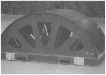
Normally, composite aircraft components are cured in the higher temperature ranges, typically at around 180°C, and in an autoclave under a pressure of up to 700 KPa. Therefore composite tooling, if used, must be able to withstand these conditions and have a glass transition temperature at least 15°C above the curing temperature. The high cross-link densities and high concentrations of polar molecular groups of such polymers result in a cured resin of high brittleness with susceptibility for moisture absorption. Repeated thermal cycling causes microcracks leading to eventual loss of vacuum integrity. In extreme cases, blistering occurs from the presence of trapped moisture. With care, however, production runs of over 100 can be achieved, and because they can be produced economically from a master, they are still popular among many manufacturing organizations. Composite tool material suppliers have in some cases developed complete systems for composite tooling that assure good tool durability, an
160 COMPOSITE MATERIALS FOR AIRCRAFT STRUCTURES
example of which is shown in Figure 5.32. Naturally, there are no concerns from differing CTEs.
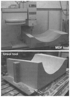
Composite tools are taken from a master model that is usually machined from computer-aided design data. Carving or splining by hand were alternative methods used in the past, however these have now largely been discarded. A variety of materials can be used for the master including polyurethane modelling board, hardwood, and medium-density fiberboard (MDF) (Fig. 5.30). The master is a positive of the component shape so that the tool can be cast directly from the surface without a transfer mold. The masters need to be handled and stored carefully because it may be intended to produce replacement tooling at some later date. Contact with moisture must be avoided because these materials are hygroscopic and will not be stable in the presence of moisture.
The tool can be a solid fiber laminate construction that is sometimes reinforced with a backing to increase stiffness. This backing may be in the form of a laminated "egg-crate" or a thick tooling compound sandwiched between the laminations. Cast epoxy can be used for smaller tools where stiffness is not a
Fig. 5.30 Medium-density fiberboard (MDF) and Ureol tooling.
COMPONENT FORM AND MANUFACTURE |
161 |
concern. These are usually filled with aluminum to increase thermal conductivity and modulus.
More recently, tooling pastes have been used whereby the paste is dispensed onto a foam or honeycomb backing structure followed by machining to the desired shape. These are suitable for manufacture of lower-temperature curing materials.
The tools will be surfaced with a high-temperature gel-coat. These sometimes contain fillers such as aluminum, ceramic, or silicone carbide to improve abrasion resistance.
5.8.3Mandrels
The interest in part integration has led to the concept of cocuring. With this concept, detail laminates are laid-up onto individual mandrels that are loaded together into an assembly mold. An example of this is the Airbus A300 fin box, which is made with pre-preg material and cured in a single autoclave cycle. The key issues for design of the mandrel system are how the mandrels will be removed after cure and how to ensure the correct compaction across all surfaces. Either flexible or rigid mandrels can be used.
Flexible mandrels can be solid or can be inflatable bags that are pressurized internally through a vent to the autoclave chamber. They are usually constructed from a polyacrylic elastomer such as Airpad. This is an uncured non-silcone rubber that can be molded into shape. The sidewalls of inflatable bag mandrels are stiffened with a reinforcing fabric such as woven carbon fiber. This produces a semi-rigid box on which the composite plies can be laid-up (Fig. 5.31). There is sufficient compliance in the mandrel to expand when exposed to internal pressure, forcing the plies against the adjacent surfaces. Removal of the mandrel
Fig. 5.31 Airpad brand inflatable tooling.
162 COMPOSITE MATERIALS FOR AIRCRAFT STRUCTURES
after cure can be achieved by applying a partial vacuum whereupon the bag collapses sufficiently for it to be withdrawn.
The durability of the Airpad material is limited, and often a replaceable nylon film is cured onto the surfaces to extend the useful life o f the mandrel.
Metal mandrels are an alternative and have an advantage in terms of durability. Aluminum is often used and, in conjunction with a steel mold, provides compaction through differential expansion. Great care has to be taken to control the dimensions such that the correct compaction and hence the correct fiber/volume fraction is achieved. Removal o f metal mandrels is less simple and even though an aluminum mandrel will shrink away from the cured part on cooldown, depending on the geometry, this ma y be insufficient to release it. In these circumstances it is necessary to use a segmented or split mandrel. These segments are joined with an adhesive that holds the mandrel together during lay-up but breaks down at the cure temperature to allow the segments to be removed individually after cure.
For complex geometries when either of the above solutions would still not allow mandrel removal, mandrels made of a soluble plaster are used. These are cast to shape for each part and melted or washed-out under high-pressure water after use. Removal rates o f the plaster tend to be low, and the economics of this restrict it to small items or where no other choice is possible.
5.9SpecialThermoplastic Techniques
5.9.1Intermediate Forms
Because o f |
their |
very high viscosity at low to moderate temperatures, it |
is significantly |
more |
difficult to impregnate a reinforcement with a thermoplastic |
Fig. 5.32 ACG "Toolbrace" tooling.
COMPONENT FORM AND MANUFACTURE |
163 |
material than with a thermoset resin. Thermoplastic composites are therefore supplied in a variety of different ready-to-use intermediate forms that may be processed through a number of standard production techniques 14 (Fig. 5.33). Considerable work has gone into developing these intermediates over the past decade. Typically, this has centred on the development of materials that have some form of a "partial impregnation," such as solvent or melt pre-pregs, film stacked pre-pregs, commingled fibers (carbon and thermoplastic fibers in a bundle or woven cloth), and powder-impregnated bundles that can be used in conjunction with contemporary thermoplastic manufacturing technology. The latter two intermediates bring fibers and matrix together in the non-molten state and are arranged such that fibers and matrix are already well mixed before processing. The comingled fibers and powder/sheath fiber bundles can be easily converted to a woven fabric by the standard weaving processes. An advantage of these two intermediates is that they are highly drapable.
5.9.2 ProcessingTechnologyof Thermoplastic Composites
The conversion of the intermediate into a final product requires only heat and pressure. No chemical conversion takes place as with thermosetting composites. The economic advantages of thermoplastic composites can be
|
|
|
|
Fiber |
|
|
--I II I i l l l l l l l l |
I l l |
|
Wovell |
|
Fiber |
|
Fabric |
|||
|
|
|
|
Polymer |
|
|
|
|
|
Fikn |
|
|
Solvmt or Melt |
|
|
|
|
|
Impregnated Prepreg |
|
|
||
|
|
|
Film Stacking |
|
|
F~erbundle |
III]Iu |
|
Reinforein~ |
||
|
P o w d e r I m p r e l ~ ~ 1 |
|
|||
Polymer |
f i l l : l i f t |
/ |
|||
|
|
||||
|
|
|
|
||
Powder |
|
|
I l I l l I I I |
|
|
|
|
|
Polymer |
||
Polymer |
|
~ |
|||
|
|
Fibers |
|||
Sheath |
- - |
|
|
|
|
Bundle~ |
Commingled/Cow oven |
|
Fibers |
||
|
Fig. 5.33 Intermediate material forms for thermoplastic composites.
164 COMPOSITE MATERIALS FOR AIRCRAFT STRUCTURES
realized through high-rate, automated, manufacturing technologies that exploit the inherent rapid processibility of the material. The processing methods that are currently being developed for continuous fiber-reinforced thermoplastic composite parts are essentially adapted either from conventional thermoset composite technology or from existing sheet-metal-forming technology. These technologies include roll-forming, filament winding, pultrusion, diaphragm-forming, compression molding, stamping, deep drawing, and folding. Some of these techniques are briefly reviewed in the following subsections. A comprehensive review of various processing operations can be found in Ref. 15 and 16.
5.9.2.1 Roll-Forming. Figure 5.34 shows a schematic diagram of rollforming.17 The method employs consecutive roll stations to progressively deform the pre-consolidated sheet into some desirable shape. The process consists of an infrared preheating station designed to bring the sheet up to the molding temperature, followed by a series of rolling stations to form and consolidate the parts. Normally, several shaping rolls are required. The first one may be heated, but at least the last one must be cool enough to solidify the composite parts. The alignment of the rollers and the tolerance of their spacing are among several critical features that affect the quality of the product.
5.9.2.2 Filament Winding. The advantage of using a thermoplastic material in the filament winding process is that in situ consolidation can be effected that avoids the lengthy post-winding cure cycle required when using
He~
Laminated Sheet Input |
Typical Section |
Fig. 5.34 Schematic diagram of roll-forming a thermoplastic composite part.
COMPONENT FORM AND MANUFACTURE |
165 |
thermosetting composites. The same basic winding equipment used for thermoset composite systems discussed earlier in this chapter can be used for thermoplastics. Modifications require the addition of a heat source to heat the pre-preg tow above its melting/softening point and a consolidation mechanism to fuse the incoming tape to the face of previously wound material. The key steps are identified as tow preheating, tow guiding, contact point heating, mandrel heating, and post-consolidation. Heating techniques such as ultrasonic, laser beam, focused infrared, conduction, and convection heating have been investigated as methods to introduce localized heating into the process. Tow tension, heated roller, and sliding devices are possible consolidation methods that can be used. Because welding and consolidation take place immediately in the local contact area, composite parts having a re-entrant shape can be made. This is not possible with a filament-wound thermosetting composite.
5.9.2.3PuItrusion. Although the pultrusion process is primarily associated with thermoset polymer composites, it is also possible to process continuous fiber-reinforced thermoplastic composites in this way. Pre-impregnated tape or commingled fiber bundles are the most usual intermediate forms that can be used in the pultrusion process. Significantly higher die temperatures are required than are necessary for thermoset pultrusion. Furthermore, while thermosets are allowed to exit the die at high temperatures (because they are chemically crosslinked and cured), thermoplastic pultruded profiles must pass through a cooling die to avoid deconsolidation on exit. The dies for thermoplastic composite pultrusion have tapering die cross-sections from entrance to exit to facilitate consolidation whereas thermoset pultrusion dies have constant cross-sections. In addition, the resin content of the material entering the die is more critical for thermoplastics than thermosets. Thermoset pultrusions enter the die with excess resin, which under these conditions is at a low viscosity, allowing it to be squeezed off at the die entrance. Thermoplastic materials, on the other hand (due to their much higher viscosity), must enter the die with a net resin content. The pultrusion of thermoplastics does not rely on a chemical reaction within the die that is time-dependent. Consequently, pultrusion speeds for thermoplastics will be faster than for thermosets.
5.9.2.4DiaphragmFormingof ThermoplasticComposites. Diaphragm
forming is also used to form thermoplastic composites, being particularly applicable to the forming of large areas with double curvature. Because the process requires far higher temperatures and pressures than the forming of thermoset pre-pregs described earlier in this chapter, the operation needs to be carried out in an autoclave or in a hydraulic press (Fig. 5.35). In the latter case, a split pressure chamber is mounted between the upper and lower platens. The unconsolidated pre-preg lay-up is sandwiched between two sealed, plastically deformable diaphragms. The diaphragms are clamped to a vacuum ring. After creating a vacuum within the composite lay-up, the entire sandwich is heated
166 COMPOSITE MATERIALS FOR AIRCRAFT STRUCTURES
Insulation
Steel Cylinder
Laminate
Vacuum~ ,
Diaphragms
|
|
|
a) |
|
|
Heated Pressm~ Vessel |
|
Compressed |
J |
|
Upper |
t |
Diaphragm |
||
Air |
u |
p + |
|
Vacuum |
|
|
Prepreg |
Lay--up
p -
Lower
Diaphragm
Vacuum
Mold
b)
Fig. 5.35 Diaphragm forming a thermoplastic composite part: a) in autoclave; b) in mold.
above the polymer melting/softening point, and pressure is applied to force the sandwich against the mold. During the processing, the diaphragms undergo a stretching action that supports the pre-preg layers and prevents wrinkling. Once forming is complete, the mold is cooled below the melting temperature of the thermoplastic resin. The diaphragms are then stripped off, and the component can be trimmed and finished. The stiffness of the diaphragm is a critical factor in achieving an optimum process. A typical cycle time of heating, pressurization, forming, and cooling might range from 40 minutes to 2 hours, depending on the tooling, heating, and cooling methods used. The actual time to shape the lay-up is typically 1 - 5 minutes.
COMPONENT FORM AND MANUFACTURE |
167 |
5.9.2.5 Compression Molding. The process of compression molding can be applied to all the various intermediate material forms. Figure 5.36a illustrates the compression molding of a fiat panel. The pre-preg lay-up is heated to melt the thermoplastic matrix; pressure is then applied to consolidate the plies together, and the laminate is cooled under pressure. The laminates can either be cooled directly within the molding press or quickly transferred to a cold-press with pressure reapplied. The latter procedure can effectively shorten the cycle time because it eliminates the period required to heat and cool the hot-press during forming. Specific profile shapes instead of fiat laminates can also be produced using this technique (Fig. 5.36b). The laminate is supported in a frame or ring that allows the heated laminate to slip between the frame under the drawing forces generated as the mold closes.
5.9.2.6 Stamp-Forming. Stamp-forming is a variation of compression molding, which is similar to the sheet-metal stamp-forming process. This technology is best suited to the forming of simply-folded shapes requiring only a minimum of deformation in the material. In this process, a consolidated flat laminate is heated in an external heater to a temperature above the melting/ softening temperature of the thermoplastic matrix. The hot laminate is then quickly transferred into an unheated mold, where it is stamped to conform to the mold geometry and allowed to cool under pressure to a temperature below the melting point of the polymer matrix (Fig. 5.37). The typical cycle time is about 2 - 3 minutes. Because the heated laminate is exposed to a lower environmental temperature before forming, the use of high closing speeds is important to successfully stamp-form the part. Either mechanical or hydraulic presses can be used.
Heater |
~ ~ ]. |
Mold |
, \ |
'/ |
, |
Ring
h,sulation
I |
I ' - |
] |
Laminate |
|
[ |
a) |
b) |
|
Fig. 5.36 Schematic diagram of compression molding of a thermoplastic composite part: a) flat panel molding; b) shaped panel molding.
168 COMPOSITE MATERIALS FOR AIRCRAFT STRUCTURES
|
\ |
l l l l |
Preheating |
\ |
|
|
|
|
|
|
t t t t |
Stamping
Die |
~ |
Metal |
|
|
Die |
Heated |
|
|
Laminate |
|
|
~ Clamping |
|
|
|
~" |
Rubber |
Fig. 5.37 Schematic diagram of stamp-forming a thermoplastic composite part.
The dies can be matched metal or single metal with a conforming rubber block. The use of matched metal dies provides improved dimensional control and surface quality on both sides of the part. Metal dies can apply higher pressures and can also be internally heated, further enhancing the quality of the final product. However, their rigidity creates a non-uniform pressure over the laminate during the forming process that makes it difficult to control wrinkling. Furthermore, it can result in varying fiber/volume fractions through the product and consequently non-uniform mechanical properties. To overcome these disadvantages, one of the metal dies can be replaced with a flexible rubber block. The remaining rigid metal die determines the final shape of the product and gives a good surface quality on the contacting face of the product, and the rubber block generates a homogeneous pressure distribution on the composite material. The flexibility of the rubber will account for any thickness mismatch or thickness variation of the product. To facilitate molding of more complex geometries, the rubber may be contoured to approximately match the shape of the rigid metal mold half. Sometimes it is beneficial to underor over-shape the rubber die to avoid or create certain high local pressures that can improve the quality of the product. Silicone rubber is usually used as the block material, which allows a relatively high processing temperature range (up to 320°C).