

5 Component Form and Manufacture
5.1Introduction
Because fiber reinforcement is essentially a one-dimensional strengthening process, a major function of the component-forming process is to orientate the fibers in the matrix in the appropriate directions and proportions to obtain the desired two-dimensional or 3-dimensional mechanical properties. The forming process must also produce the shape of the component and develop the required properties of the matrix and the fiber/matrix bond. The forming process must not damage the fibers and must ensure that they are reasonably evenly distributed in a matrix, free from significant voiding or from large areas devoid of fibers.
The simplest method that satisfies these requirements is to infiltrate an appropriately aligned fiber bed with a liquid, which is then converted by chemical reaction (in the case of thermosets) or simply by cooling (in the case of thermoplastics) to form a continuous solid matrix with the desired properties. Techniques based on liquid resin are known as liquid molding, with several subcategories according to various modifications of the process.
Alternatively, sheets of aligned fibers may be pre-coated with matrix precursor and the continuous matrix formed by flowing the coatings together (and curing, if a thermoset matrix) under heat and pressure. In this widely used form, the material is known as pre-preg (pre-impregnated).
There are several methods that can be used to arrange the fibers when forming the composite structure. The main method for the manufacture of aircraft components is laminating woven cloth, or aligned fiber sheets, with the fibers orientated in appropriate directions in each layer.
There are also several methods based on continuous fiber tow or yarn; these include:
(1)filament winding onto a rotating mandrel; (2) braiding onto a rotating mandrel (the process of braiding is covered in detail in Chapter 14); (3) tow placement; and (4) pultrusion.
The main differences between the use of thermosets and thermoplastic matrices are the need for extended times to cure (cross-link) the thermosets and the relatively high viscosities of the thermoplastics melts and the consequential requirement for high processing temperatures and pressures. Table 5.1 lists generic aircraft components made using these manufacturing procedures.
113
114 COMPOSITE MATERIALS FOR AIRCRAFT STRUCTURES
Table 5.1 Typical Aircraft Fiber Composite Forms Made by the Different Techniques, as Listed
Type of Structure
Laminates
Sheets, thick monolithic Sheets, integrally stiffened Sandwich panels
Shells
Beams Complex forms
Filament Wound
Closed shells
Open shells
Tubes
Secondary formed tubes
Braided
Tubes
Complex tubes
Closed shells
Secondary formed
Tow Placed
See laminates
Complex wraps
Pultrusion
Beams
Typical Application
Wing skins Tail skins
Control surfaces, floor sections Fuselage sections
Spars/ribs
Aerofoils
Pressure vessels
Radomes
Rocket motors
Drive shafts
Helicopter blades
Drive shafts
Curved pipes
Truss joints
Ducts
Pressure vessels
Fuselage frames
Aircraft propellers
Helicopter blades
See laminates
Grips
Shafts
Ducts
Floor beams
Stringers
Spars
Ribs
Longerons
Considerable structural and cost efficiency can be obtained by using the composite in the most highly stressed regions, for example, in the upper and lower surfaces o f components subject to bending or buckling. This is achieved by using a sandwich construction, as also listed in Table 5.1, with the composite laminate forming the outer skins, which are bonded to a metallic or polymeric
COMPONENT FORM AND MANUFACTURE |
115 |
composite honeycomb or polymeric foam core. The metallic honeycomb is generally an aluminum alloy such as 5052, often with a coating or anodized layer to resist corrosion. The composite honeycomb would generally be glassreinforced epoxy or phenolic; however, the most usual honeycomb material is Nomex, which is the trade name for a composite based on random meta-aramid fibers in a phenolic matrix. The foam core used for aerospace applications is generally made of PVC, but this material is not generally used in applications exposed to high temperatures. Polyetherimide (PEI) and polymethacrylimide (PMI) polyimide foams are alternative cores for higher-temperature applications.
This chapter deals primarily with pre-preg laminating procedures in some detail because this is the prime method for manufacturing aircraft composite components. Methods based on liquid resin are then considered, followed by details of the various processes, resin transfer and infusion, and filament winding and pultrusion. Finally, the particular processes for manufacturing with thermoplastic resins are covered.
5,2 Outline of General Laminating Procedures
Most reinforced-plastic components based on long fibers are manufactured by some form of laminating procedure. 1 In this process, sheets of reinforcement, pre-coated with resin (pre-preg) or with resin freshly applied, are forced against the surface of a mold under the required conditions of pressure, temperature, and time. Chapter 3 provides details of some of the cloth materials available, and details of the pre-pregging process are provided later in this chapter.
5.2.1 OpenDie Molding
Open die molding involves the use of only one mold surface, over which the layers of fiber are placed or "laid-up." If dry cloth is used, the resin may be applied by brushing or spraying. With care and suitable materials, this method (which is still widely used outside the aircraft industry) can produce good-quality parts. However, handling wet resins can be messy and can raise occupational health and safety (OH&S) concerns. In addition, a particular concern with the use of wet lay-up in aircraft-part production is the lack of repeatability of the process, especially the control of resin content and therefore the weight, thickness, and mechanical properties. Some smaller companies, notably in the German Glider Industry, have adopted wet pre-preg dispensing machines, which saturate reinforcement fabric on demand with a controlled amount of liquid resin, normally epoxy, and hardener. This solution is cheap and flexible, and it does not require cold storage.
Various methods are engaged to apply pressure to consolidate the lay-up. In contact molding, which is generally used only for fairly low-stress applications of
116 COMPOSITE MATERIALS FOR AIRCRAFT STRUCTURES
glass/polyester composites, the pressure is developed by hand-rolling over a sheet of plastic film placed over the surface of the lay-up.
The bag procedure involves the use of a flexible plastic membrane that is formed over the surface of the lay-up to form a vacuum-tight bag. In vacuum bagging, the bag is evacuated and atmospheric pressure used to consolidate the lay-up against the surface of the mold. The vacuum initially removes most of the air and volatile materials. Vacuum bagging is an inexpensive and versatile procedure; however, it can provide only limited consolidation pressure and may produce voided laminates due to the enlargement of the bubbles (formed by any residual gases or volatile material) trapped in the resin in regions where the bag is unable to apply pressure, for example, because of local bridging. To minimize this problem, autoclave procedures, described later, are used to manufacture most of the high-quality laminates used in the aircraft industry.
Alternatively, pressure may be applied to the surface of an open mold by means of a flexible plunger mounted in a press, by gas-bags, or by thermal expansion of an entrapped rubber or metallic insert.
Temperature, generally required to cure the resin, can be applied to the open mold in various ways, including external methods such as hot-air blowers and ovens or internally by electric elements or steam or oil pipes buried in the mold. Temperatures up to 180 °C may be required in aerospace-grade epoxy resin systems.
5.2.2 CompressionMolding
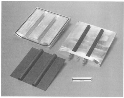
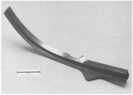
Compression or matched-die molding involves the use of matching male and female dies that close to form a cavity of the shape of the component (Fig. 5.1). The dies, generally made of tool steel, can be internally heated, if required, by electric elements or steam, or hot oil pipes. The fiber layers are placed over the lower mold section, and the two halves of the mold are brought together in a press. Lands built into the mold usually control the thickness of the part. Advantages of matched-die molding include excellent dimensional control; highquality surface finish, produced on both surfaces; high production rates; and good consolidation and high fiber content.
However, the cost of the matching dies (with hardened faces) is very high, and the size of the available hydraulic presses used to apply the closing pressure limits the size of parts that can be produced.
Wet laminating procedures may be used, in which case the dry fiber is laid in the mold and the resin added. High-quality fiber composite components are generally based on the use of pre-pregs or by the use of a solid, but uncured, resin film that is laid on the mold surface, followed by dry fiber layers or a fiber preform.
Alternatively, a liquid resin can be injected into the sealed and evacuated mold cavity, as discussed later.
COMPONENT FORM AND MANUFACTURE |
117 |
Fig. 5.1 Matched-die mold and resulting top-hat stiffened component.
5.2.3 Wrapping
Wrapping is an alternative procedure to filament winding, described later, for producing tubular components. A pre-preg sheet, either wrap sheet or cloth, is wrapped onto a removable metal mandrel and cured under pressure. Special machines are available to perform the wrapping operations. The pressure during an elevated temperature cure may be applied by the use of shrink film (applied by a tape-winding machine), vacuum bag, or autoclave. Alternatively, a siliconrubber bladder may be placed over the mandrel before the wrapping of the laminate. Pressure is applied to the laminate through-inflation of the bladder that forces the laminate against an outer mold surface. This technique is often used to make fishing rods, golf clubs, and tennis rackets.
5.3Laminating Procedures For Aircraft-Grade Composite Components
Major aircraft manufacturers and their subcontractors, especially in the United States, use B-staged epoxy pre-preg as their preferred material form. In this material, the reinforcement is pre-impregnated by a supplier with a resin already
118 COMPOSITE MATERIALS FOR AIRCRAFT STRUCTURES
containing hardener. 2 This has been partially cured (B-staged) such that the resin does not flow at room temperature, but at the same time it remains tacky (sticky to the touch). B-staged epoxy pre-pregs are normally staged (partially cured) to about 15% of full cure for hand lay-up, and up to 25% for automated lay-up. To protect this material and keep it from sticking to itself, a backing or release film is added to at least one side of the pre-preg before it is rolled up for storage or transport.
5.3.1Pre-Preg Production
A pre-preg can be made incorporating a variety of reinforcement fabrics and fiber types. Although it can be produced by the component fabricator, it is normally purchased from a materials-supply company. The following material forms are available as carbon/epoxy pre-pregs.
Woven hi-directional cloth pre-preg is most commonly made from plain weave or satin weave fabrics, 0.2-0.4 mm thick and up to 1200 mm wide. One common method of pre-impregnation is to infuse the cloth with matrix resin diluted with solvent to lower its viscosity. The pre-preg then passes through a heating tower to remove the solvent and stage the resin. The newer hot-melt method (See Fig. 5.2) involves first continuously casting a B-staged resin film on a non-stick backing film of coated paper or polymer. A doctor blade is used to control the thickness of the resin film applied (the same method used to make adhesive film). The reinforcement is then sandwiched between two of these films as it passes through a pair of heated rollers. This process has an advantage over the solvent process in that it produces lower volatile emissions.
Unidirectional pre-preg (warp sheet) is made by spreading and collimating many fiber tows (typically around 104 fibers in each tow) into a uniform sheet of
~ TopReel Poper
Rber |
|
|
|
|
|
|
|
|
|
Rolls |
|
Doctor |
|
Heat ~ |
Cool |
- ~ |
Pr~reg |
Blade- ~ |
|
Take-up Reel |
|||
|
|
|
|
|
|
~ f . . ~ |
~- Filming Plate |
Plate |
|
|
|
Fig. 5.2 Schematic illustration of hot-melt film pre-pregging process. Adapted from Ref. 2.
COMPONENT FORM AND MANUFACTURE |
119 |
parallel fibers typically 0.125-0.25 m m thick and 300 or 600 m m wide. This is immediately pre-impregnated. Unidirectional pre-preg is the cheapest to make, and it provides laminates with the best mechanical properties. However, it may be difficult to lay into double-curved shapes. Other types of reinforcement architecture, such as multi-axial warp knit (also known as non-crimp, knitted, or stitched) fabrics can also be pre-impregnated, but the process becomes increasingly difficult as the fabric becomes thicker.
The pre-preg with its non-stick backing films is then inspected for resin content, which is typically between 34% and 42% by weight for carbon prepregs, wound onto a roll, and sealed to prevent the absorption of water vapor. Some pre-pregs have up to 15% more resin than is required to form a laminate with the desired fiber/volume fraction. With these pre-pregs, the resin is required to bleed out of the laminate during curing. Low-bleed or non-bleed pre-pregs with a more viscous resin are now more popular.
The standard pre-preg thickness for unidirectional materials is of the order of 0.125 mm. More recently, to cut costs, much larger tows are being used, resulting in much thicker pre-pregs; however, because it is more difficult to maintain fiber alignment in thick tows, there is some reduction in mechanical properties of the finished composite.
5.3.2 Pre-Preg Transport and Storage
The major disadvantage of pre-preg (apart from the extra cost of creating it from the fiber and resin) is that once the hardener has been added, the resin begins to react. Therefore the material normally only has a limited "shelf' (storage) life and "shop" (usage) life before the resin has reacted sufficiently for the pre-preg to become stiff and intractable for lay-up, or for the quality of the resulting composite to suffer. Most pre-pregs need to be stored in a freezer, typically at around - 2 0 ° C , which halts or at least greatly slows down the curing reaction in the resin. Pre-pregs generally used in aerospace are cured at elevated temperatures, typically 120°C or 180°C for epoxy resins. Because the resin is designed to react at elevated temperature, the supplier can normally guarantee a shelf (freezer) life of 6 months to a year, and a shop life ("out" life at room temperature) of at least 2 weeks.
If the distance from the supplier to the user is long, the pre-preg will need to be shipped in refrigerated shipping containers; or for smaller lots, in insulated packages containing dry ice (frozen carbon dioxide).
5.3.3 Cutting and Kitting
When pre-preg is required for use, it is thawed to room temperature before being removed from its bag to avoid picking up condensation. The pre-preg is then moved into the cutting room, which like the lay-up room is maintained as a "clean room," free of dust and with controlled temperature (around 20°C) and
120 COMPOSITE MATERIALS FOR AIRCRAFT STRUCTURES
humidity (e.g., between 5 0 - 7 0 % RH). The pre-preg is then unrolled onto the cutting table, with its backing paper still in place. Plies of the required size, shape, and fiber orientation are then cut from the roll; as an example, Figure 5.3 shows a ply stack for a wing rib. This can be done by hand-using a template, or with a die in a roller press; in all but the smallest operations, this is usually done by a numerically controlled flat-bed cutter similar to those used in the textile industry. Cutting is usually achieved using an oscillating blade, but sharp "draw knife" blades as well as lasers or water jets are also used. Some cutters can cut multiple layers of fabric. Some flat-bed cutters can also label the plies automatically. The various ply shapes are then labelled, if necessary, and assembled as part of a kit containing all the plies for a component, which may be delivered directly to the lay-up room or sealed and stored in a plastic bag in the freezer for later use.
Abrasive water jet cutting uses a high-pressure water stream, perhaps up to 400 MPa, which is forced through a small sapphire orifice to produce a supersonic jet travelling at speeds up to 900 m s-1, carrying abrasive particles to form a powerful cutting jet. Most materials can be machined with the water jet's ability to revolve with the robotic end effector. The critical process parameters are speed; stand-off distance; impact angle; water-jet pressure; water flow rate; orifice diameter; abrasive particle shape, hardness and size; and nozzle mixing tube geometry and material. Generally, the impact angle can be optimized to produce the maximum removal rate. The work-piece material should be softer than the abrasive compound. Oscillation of the cutting head can also influence the quality of the cut.
Laser cutting can be considered a thermal process as a portion of the beam energy is absorbed by the surface material, and this energy raises the temperature
o o o o o ° °
Sta~l~" °"
C e n t e r
Fig. 5.3 Schematic diagram of a typical ply stack for a wing rib.
COMPONENT FORM AND MANUFACTURE |
121 |
of the material. A sufficient amount of such energy will cause local decomposition of the material. Some compromise is required when focussing the laser beam as minimum spot size (a result of using short focal length lenses) is achieved at the expense of depth of field. The creation of thermal energy during cutting can produce problems in the course of dealing with standard epoxy prepreg systems producing local cure and toxic vapors.
All methods of cutting for complex geometry flat shapes must be capable of operation with either a standard robot or gantry-type equipment.
5.3.4 Lay-Up
Most aerospace components are still laid-up by skilled labor, although considerable efforts are being made to automate or mechanize the process, as described in the subsequent sections. Hand lay-up is very versatile because human hands make excellent grippers, eyes marvellous sensors, and the brain a powerful process control and quality control unit! Any residual dust or resin from previous use is cleaned off before a thin layer of release agent is applied to the surface, where necessary. The mold will then be moved into the lay-up clean room.
The pre-preg plies are then applied to the mold in the correct position, orientation, and sequence according to a set of instructions sometimes called a ply book; these instructions may be viewed on a computer screen. The ply is located on the surface by reference to markings on the mold or with the aid of a rigid or flexible template. Many companies now have lay-up stations where an overhead projector rapidly scans a low-power laser beam to "draw" the outline of each ply on the mold surface. These machines can also project instructions for ply lay-up onto the mold.
Typically, the lower backing paper is removed by the operator before lay-up, and the upper one after positioning and consolidating using rollers or other simple tools. For larger plies, two or more operators may be required to handle and position the tacky pre-preg. Where the mold surface is doubly-curved, the prepreg needs to be further distorted, enabling it to fit the surface.
Different types of material may be combined in the same lay-up as long as the materials are compatible. For instance, in sandwich structures, aluminium or Nomex honeycomb and adhesive films will normally be combined with carbonepoxy pre-preg to form the structure. Different fibers such as glass and carbon may be combined to form hybrid lay-ups, and different reinforcement arrangements such as unidirectional tape and woven fabric may be combined.
5.3.5 Automated Forming of Pre-Preg Stacks
To reduce lay-up times and consequently labor costs, automated or semiautomated methods have recently been introduced to aircraft component production lines.
122 COMPOSITE MATERIALS FOR AIRCRAFT STRUCTURES
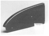
Instead of shaping and consolidating (laying up) each ply separately by hand, a flat stack can be assembled by manual or mechanical means. This flat stack can then be formed into the required shape using various methods; pressing, stamping, or diaphragm-forming. One version of the diaphragm-forming process is illustrated in Figure 5.4. A flat pre-preg stack is laid up and placed over a maleforming die. A diaphragm is fitted and sealed to the forming box. A vacuum is then applied to the box cavity. Because they are not extensible in the fiber direction, the plies must deform by shear to conform to the shape of the tool. It may be necessary to heat the fiat pre-preg stack to a temperature above room temperature to assist forming. An infrared heating source is often used for this purpose.
This process is most attractive for deep draws, and consequently the shear deformation required can be considerable. There are three main modes of deformation: intraply shear (a trellising action in which the fiber tows pivot at the crossover points), slippage between plies, and ply out-of-plane bending. The main problem is to avoid wrinkling of the plies caused by the development of compressive residual stresses. Computer simulation to assist in predicting the optimum conditions for forming is a recent development discussed later in this chapter.
5.3.6 Automated Lay-Up
Lay-up of large components such as wing skins requires automation because, owing to the time required for hand lay-up, materials may be close to their out-life when the task is nearing completion.
I
Fig. 5.4 Schematic diagram of the diaphragm-forming process; below, carbon fiber-epoxy rib made using this process.
COMPONENT FORM AND MANUFACTURE |
123 |
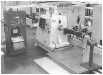
There are two established approaches to automating the lay-up process: automated tape layers (ATL) and automated tow placement (ATP) machines. ATL machines normally consist of a gantry with a dispensing head that is free to move over the surface of the tool. Generally, unidirectional pre-preg tape is placed onto the surface (Fig. 5.5) according to a programmed routine.
As the tape is placed on the surface, the backing layer is stripped away, and the surface of the tool may be heated to aid tack of the pre-preg. Tape width is typically around 300 mm, and the lay-down rate is of the order of 50 m m i n - 1. Advanced ATLs are capable of laying tape onto a highly contoured surface. However, these machines are very costly and can be justified only where long runs of expensive components, such as tail or wing skins, are to be made.
ATLs are also being developed for use with thermoplastic pre-pregs. In this application, a gas flame or laser is used to heat the tape as it is laid down and a consolidation roller is then used to form the composite layer.
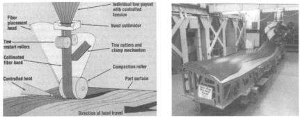
The limitations to the capability of ATL machines to manufacture more complex shapes has led to the development of automatic tow placement (ATP) systems. These machines lay down multiple pre-preg tows and are able to stop, cut, and restart individual fiber tows. A multi-axis manipulator arrays a group of pre-preg tows into a continuous band and compacts them against the surface of the lay-up tool. This allows more complex shapes to be fabricated, including layup onto relatively severe and complex curves and the steering of tows into curved trajectories. Heat and pressure are used to ensure proper adhesion and consolidation of the material.
ATPs offer the potential for greater structural optimization by locating fiber where it is most effective. Some systems are combined with a spindle, (Fig. 5.6) to allow lay-up of closed shapes such as ducts, combining the advantages of both filament winding and automated tape lay-up while alleviating some of the problems associated with each. However, these are, so far, even more expensive to purchase and operate and have been limited to use on military aircraft
Fig. 5.5 Schematic diagram of an automatic tape-laying process (left) and a typical product (right).
124 COMPOSITE MATERIALS FOR AIRCRAFT STRUCTURES
Fig. 5.6 An automatic tape placement system in use at Bell Helicopter from Automated Dynamics Corporation literature.
programs and in cases where the complexity of shape means that the part cannot be practicably fabricated in any other way.
5.3.7 Bagging
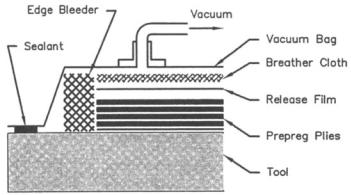
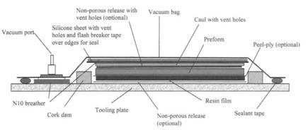
After all plies have been laid-up and inspected, the lay-up is prepared for curing. An autoclave or vacuum bag will be applied over the surface of the lay-up and sealed to the mold, so that a consolidating pressure can be applied during cure by evacuating the space under the bag, and/or by increasing the outside pressure. As illustrated in Figure. 5.7, the bagging process uses a number of different materials. These include:
• |
Release f i l m - - a smooth non-stick film often made from fluro-polymers, placed |
|
over the lay-up, which may be perforated to allow passage of gases or resin |
• |
Breather fabric--transmits gases even under pressure and is used to allow |
|
gases to flow from all over the part to the vacuum fitting |
• |
Bleeder fabric--used to soak up excess resin, especially in high-bleed |
|
pre-pregs |
•Vacuum bag film, normally nylon
•Mastic tape -- also called tacky tape and often made from butyl rubber; used to seal the edge of the bag to the mold
In addition, for surfaces to be bonded, a peel ply (non-bonding woven cloth, such as nylon) is placed on the surface of the lay-up. During the cure this is incorporated into the surface resin and is subsequently peeled off to create a clean, roughened surface that is ready for adhesive bonding.
126 COMPOSITE MATERIALS FOR AIRCRAFT STRUCTURES
the composite is sufficiently high. As a typical example, a carbon/epoxy composite cured at 180°C for 2 hours might have a glass transition temperature (Tg) of 200°C when dry, but only 160°C when saturated with moisture. This would allow the composite to be used at a maximum service temperature of around 135°C.
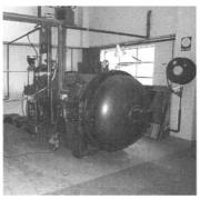
As mentioned earlier, composites may be cured in an oven under a vacuum bag, but the best results come from the use of pressure above one atmosphere (compaction pressure), usually generated in an autoclave. The autoclave is basically a very large, internally heated pressure vessel, with internal connections for vacuum hoses and sensors such as thermocouples (Fig. 5.8). The autoclave is usually computer controlled, and often pressurized with nitrogen or carbon dioxide to reduce the risk of an internal fire. A standard machine for epoxy composites will be capable of temperatures over 200°C and pressures over 700 KPa. Autoclaves for processing thermoplastic composites or hightemperature thermoset composites may be capable of 400°C and 1200 KPa or more. The part is normally heated by convection of heat from the fan-forced air circulation, although electrically heated molds are sometimes used. Although more costly, there are several advantages in heating the mold, including more rapid and uniform heating and the ability to use high temperatures as the walls of the autoclave remain cool.
Normally the lay-up will be under vacuum from the time it leaves the lay-up room and while it is loaded into the autoclave, to keep the lay-up in position and help remove air and volatiles. The vacuum and sensor connections will be checked before the autoclave door is closed and the cycle commences. Pressurization and heating will begin immediately, and the target pressure will be reached in less than 30 minutes whereas, in thick parts, the target temperature may not be reached for several hours. After more than 100 KPa (gauge) pressure has been reached in the autoclave, the space under the vacuum bag is vented
/ ~ |
utociavewall |
|
basMCipdate |
||
II ~ . |
/ |
,.'"°'GI |
Vacuum ~ |
tt |
"? |
Fig. 5.8 Layout of an autoclave and, right, a small typical autoclave.
COMPONENT FORM AND MANUFACTURE |
127 |
(connected to the atmosphere) to discourage the growth of existing bubbles and the generation of new bubbles, from entrapped gases and volatiles, in the resin as it is heated. Heat-up and cool-down rates are controlled to ensure even curing throughout the part and to reduce the possibility of residual stresses causing structural deficiencies or distortions.
The viscosity of the resin falls with increasing temperature until the resin begins to chemically cross-link (gel). It is important that full pressure is applied before gelation occurs to allow removal of entrapped gases and removal of excess resin.
Under some circumstances, a dwell is incorporated (isothermal hold), as shown in Figure 5.9, to prolong the time for consolidation and volatile removal. The hold also pre-reacts the resin and reduces the danger of large damaging exothermic reactions that can occur in thick laminates, for example, over 50 plies thick. A hold will also allow the temperature to become more uniform; this is very important in components with large variations in thickness.
The need for complex heating/pressure cycles is important for earlier, less viscous epoxy resins and high-temperature resins because this is necessary to accommodate the requirements of the chemical reactions and to ensure that the resin viscosity is optimum when pressure is increased. Most modern non-bleed epoxy pre-pregs, however, can be processed with a simple "straight-up" cure cycle, provided that the component is not too thick or complex.
I f an autoclave is not available, compaction pressure may also be applied by an inflated rubber bladder or by materials with a high coefficient of thermal expansion (CTE) such as silicone rubber, used in conjunction with matched mold tooling. The expansion force generated by these arrangements requires that the
200
175 -
150- ~125100--
75
50,
|
[ |
I |
! |
0 |
50 |
100 |
150 |
Tmle (rain)
Fig. 5.9 Typical autoclave cycle incorporating equilibration in thick lay-ups.
.:-7
200 250
a dwell to allow temperature
128 COMPOSITE MATERIALS FOR AIRCRAFT STRUCTURES
tooling be stiff to resist the bending forces applied to the tool. (Bending forces are low in autoclave tooling because the pressure acts on all sides.)
Autoclave molds must be vacuum tight and free of distortions under temperature. Ideally, they should have a low thermal mass to avoid slow heating and cooling and should have a low CTE, similar to that of the laminate.
5.3.9 Cocuring of Complex Components
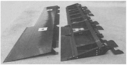
Complex integrally stiffened components, such as those shown in Figure 5.10, can be manufactured using internal pressurization3 (Fig. 5.11). There are essentially two methods of applying internal pressure: thermal expansion of a rubber or metallic mandrel, and expansion under autoclave pressure of a rubber bladder. In both cases, the approach is to wrap pre-preg around the internal mandrel, which is inserted into an outer mold containing the outer skins. As shown in Figure 5.10, it may be desirable to arrange for one, usually the top outer skin, to be removable to allow equipment to be installed or for inspection purposes. This can be achieved by introducing a release film between the outer (removable) skin lay-up and the substructure. The outer skin, though cured at the same time as the substructure, can be separated, the release film removed, and the skin mechanically fastened or bonded in a secondary operation.
5.3.10 Processing Problems
The main processing problems encountered in autoclave molding include overheating (caused by excessive exothermic reactions), porosity, resin-rich
Fig. 5.10 Cocured control surface components with integral lower skin and ribs and removable top skin. Courtesy of CRC-ACS.
|
COMPONENT FORM AND MANUFACTURE |
129 |
|
|
Cocured |
Vacuum I |
|
|
Pump |
|
|
Lightweight |
Spar |
- ~ |
|
Steel |
|
\ |
|
Tooling - - ~ |
|
|
|
T t |
B~] |
•B |
Cavities Open |
I~Jl] |
] " |
Skins |
I . - - |
H H - - |
- - H l l ~ |
to Autoclove |
~ BB ~ |
/ |
|
/ / ~ , B H - |
- ~ |
' / "-'HI-- |
Pressure |
- - I I - - |
/ |
|
" |
" |
Silicone R u b b e r
Pressure Bogs
Fig. 5.11 Schematic diagram of the tooling used to make a cocured carbon/epoxy wing structure, using rubber bladder expansion for internal pressurization. Adapted from Ref. 3.
areas, resin-dry areas, poor surface finish, insufficient consolidation, uneven cure, and distortion.
Many of the problems can be resolved by correct timing of application of temperature and pressure and use of pre-preg materials with a wide processing window with (ideally) low exothermic cures.
The formation of voids is generally caused by the entrapment of volatiles, water, and air that have remained after debulking. At the high processing temperatures in the autoclave, more solvents are liberated, and the volume of the solvents and other entrapped gases increases. To avoid the formation of severe porosity, it is necessary that the hydrostatic pressure in the resin before gelation exceeds the partial pressure of the gases, allowing them to be expelled. Once the resin gels no further, void removal or consolidation is possible. Water is often considered to be the main cause of void formation so that the applied pressure needs to exceed the partial pressure of the water. 2
While a low temperature hold is often used to increase the time at low resin viscosity for the reasons stated above, excessive pressure or over-efficient resin-bleed when the resin viscosity is low may lead to dry spots. Resin-rich areas result when areas in the lay-up have lower resistance to resin-flow and insufficient pressure is applied before gelation.
130 COMPOSITEMATERIALSFORAIRCRAFTSTRUCTURES
To reduce surface porosity, a surfacing resin film or fine glass/epoxy scrim ply may be placed on the mold surface before the pre-preg is placed.
The use of honeycomb core in the composite component can result in several problems, of which the most common is core-crushing. The reason for this is illustrated in Figure 5.12, which shows how a lateral force can arise in an autoclave, causing inward collapse of the core. 2 Methods for avoiding this problem include the use of reduced pressure in the autoclave (reduced from 700 to 300 KPa with a concomitant reduction in laminate quality, however) and use of friction grips to prevent the inner pre-preg skin sliding inwards. The gripped skin region must be surplus to the component and must be removed after processing.
Distortion can be a serious problem, and can arise from uneven cure, unbalanced fiber lay-ups, or the expansion differential between the composite
- Edgeband Chomfer.~
. f " " \
a) |
HoneycombCore ~ |
"~" |
"J" |
t |
t |
l |
t e |
b) |
Tool Reaction |
|
|
Fig. 5.12 Schematic diagram, showing a) a typical honeycomb arrangement incorporating a chamfer and b) the origin of lateral crushing forces. Adapted from Ref. 2.
COMPONENT FORM AND MANUFACTURE |
131 |
part and the tooling. It will be found that long parts such as spars may appear to have "grown" with respect to the tooling, especially if this is made of a high-CTE material such as steel or aluminum. This phenomenon occurs because the resin is solidified at the curing temperature, and, compared with the tool, the composite shrinks little during cooling. This also can make it difficult to remove some complex components from their mold without damage.
Parts such as "C" sections made on male mandrels may grip the mandrel due to a condition known as spring-in, in which composite angles close up slightly (about 1°) during cool-down because of CTE differences between the resin and fiber. Allowance has to be made in the tool design to compensate for this.
5.3.11Debagging, Finishing, and Painting
The part is normally cooled down to below 60°C before it is removed from the autoclave. The bagging layers are stripped off, and the part is carefully separated from the mold. If the release coating is imperfect or the mold does not have sufficient draught angle for deep parts, this may present processing difficulties.
The part should be smooth on the tool side, but unless matched molds are used, there will be some texture or roughness on the bag side of the part; however, this is minimized if a stiff canl plate is used. Due to slight variations in pre-preg fiber areal weight and resin contents, and in resin-bleed during curing, it is difficult to specify the thickness of a pre-preg part to less than about _+5%. This becomes a serious concern in thicker parts such as wing skins, where the choice may be between having a smooth outside surface with the correct aerodynamic contour (outer mold line tooling), and controlling the inner surface dimensions (inner mold line tooling) to allow easy assembly to the substructure.
Any surface blemishes may need to be filled with special putty. For epoxy composites, a typical paint scheme is an epoxy primer coat followed by a polyurethane topcoat. Any residue from the release coating applied to the mold may cause problems with poor adhesion of the paint. For this reason, many parts may be abraded lightly on the surface before painting.
Painting may either be carried out by traditional hand-operated methods or with robots. Robotic painting is normally controlled by computer-aided-design- generated off-line process trajectories. Computer modelling and test simulations can verify the programs before production commitment. Paint application robotics can vary the paint thickness applied that would be specified to suit the service environment. Contemporary systems for automatic paint spraying can be applied to a series of small parts through to a working envelope of up to 3 million cubic feet using gantry-mounted robots.
5.3.12 Trimming and Drilling
Increasingly, trimming and drilling processes4 are also being carried out automatically by robots.5
132 COMPOSITE MATERIALS FOR AIRCRAFT STRUCTURES
Some of the attractions of applying automation to these kind of applications are inclusion of a vision system for part recognition, elimination of jigs and templates, high speed and accuracy, and flexibility and in-process inspection.
Routing refers to the shaping of apertures or edge-trimming of components in flat and shaped panels. Robotic manipulation of routing heads with the appropriate cutting device can offer a low-cost solution, particularly when the article is of complex geometry. With automatic tool changers, a robot cell can perform a multitude of functions such as drilling holes and inserting bushes.
Trimming of the part can also be carried out using a water-jet cutter. The prime attractions of water-jet cutting of a cured composite are the negligible force on the work-piece (such that tooling is simplified) and elimination of edge delamination.
One of the more time-consuming operations in aerospace manufacture is the drilling of panels and subsequent fastener installation. Use of six-axis robots enables the most complex components such as nacelles to be automatically fastened. All the power supplies associated with any tooling, electrical and pneumatic, are automatically connected via the face-plate at the end of the robot arm. Robot-drilling and combined countersinking can be achieved in a matter of a few seconds for each hole. These systems are the same as those used for metal assemblies; however, drill-bit configuration depends on the material being drilled. Because composite structures are often attached to metal components, the bit has to be chosen such that it satisfactorily drills both materials. This is usually achieved with a carbide-tipped tool.
5.4LiquidResin Molding Techniques
5.4.1Resin Transfer Molding
The resin transfer molding (RTM) process shown in Figure 5.13 involves first placing the dry fabric preform into the cavity of a matched mold and then filling the mold and hence the preform with liquid resin. The mold and resin are typically preheated before injection. After injection, the mold temperature is increased to cure the part. In some cases, the resin is injected into a mold that has been preheated to the cure temperature. The resin preheat, injection time, and mold temperatures are set by the characteristics of the resin being used. If the temperature(s) is too high, the resin will gel before the mold is filled; if too low, then the resin viscosity may be too high to permit flow through the preform.
A vacuum is typically applied at the exit port to evacuate air and any moisture from the mold/preform before injection. Injection pressures of around 700 KPa are usual. The application of a vacuum during injection is useful to prevent void entrapment and also supplements the injection pressure; however, care needs to be taken that the injection temperature is not above the resin boiling point when the resin is under vacuum. This will lead to high and unacceptable porosity.
COMPONENT FORM AND MANUFACTURE |
133 |
|||
Vacuum |
__1 |
Resin |
I |
, |
Pump J |
[ ~ |
Trap |
I |
|
Resin |
/ |
|
I |
I |
Reservoir |
|
|
|
|
ro.oro |
|
|
|
t |
Seal
Heating
Fig. 5.13 Resin transfer molding (RTM) process.
5.4.2 Materials Systems
A large range of resins can be used for RTM, including polyesters, vinyl esters, epoxies, bismaleimides (BMIs), phenolics, and cyanate esters. Resin systems for RTM are supplied either as one-component (resin already mixed with hardener) or two-component systems.
The selection of a resin will be influenced by the suitability of its viscosity for a particular molding and the required fiber/volume fraction. For low fiber/ volume moldings (around 40%), resin viscosities up to 3500 centipoise are suitable; however, for higher fiber/volume fractions, such as are usually required for aerospace structures, the viscosity should be less than 500 centipoise.
To maximize pot-life, the resin injection temperature is usually less than the preheat temperature of the mold. Material suppliers will normally provide isothermal viscosity curves for RTM resins such as those shown in Figure 5.14, allowing the optimum injection and mold temperatures to be selected by the molder.
Preforms may be made up of various reinforcements such as fabrics, braids, and other advanced textiles. Preforms are usually fabricated by using a "tackifier" or binder in the reinforcement at around 2 - 5 % by volume. The shape is formed and consolidated on a mandrel with the application of heat and pressure (usually vacuum pressure) before it is loaded in the mold. The action of closing the mold will increase the compaction and, correspondingly, the final achievable fiber/ volume fraction. Fiber/volume fractions up to 70% are achievable with certain "high-nesting" reinforcements.
When high injection pressures are used, the possibility of fiber-wash (i.e., reinforcement distortion) exists. Loose weaves and unidirectional reinforcements will have a greater tendency to fiber-wash than tightly woven performs, such as plain weaves. Additionally, high injection pressures will cause an increase in resin flow speed between tows, without complete fiber wetting, leading to voids
134 COMPOSITE MATERIALS FOR AIRCRAFT STRUCTURES
1,000,000
100,000
|
10,000 |
|
|
V0 |
1,000 |
|
|
rt |
|
|
|
o |
100 |
, |
I 140"F I ~ |
~ ~ |
|||
. m |
|
|
|
w |
|
|
|
ow |
10 |
|
|
2 4 0
Time(minutes)
Fig. 5.14 T y p i c a l i s o t h e r m a l d y n a m i c viscosit y curve s for an R T M resin.
within the tow bundles. Alternatively, a pressure that is too low can result in voids between tows.
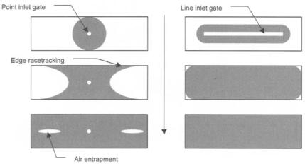
The flow of the resin through the preform can be simulated using computer models. These help to establish the optimum injection pressures and predict irregular flow fronts that can trap air and cause dry spots. Generally, the highest pressure that can be used without causing significant mold deflections is sought. The models treat the flow through the preform as flow through a porous medium. In such a material, the flow velocity v and the pressure in fluid p are coupled via the generalized Darcy's law:
v = - ( K ) • (Ap) |
(5.1) |
Here ~7 is the resin viscosity and K is the preform permeability.6
5.4.3 Tooling Systems
Tooling for RTM is similar to other closed (matched die) molds in many respects. The mold determines both the inside and outside geometry of the part. For most composite components, the outside mold line may not be critical and may be uncontrolled. However, in RTM, the cavity always needs to be controlled, otherwise processing difficulties can be experienced. Too much "pinch" on the preform will affect permeability and hence resin flow and may lead to dry spots. For this reason, all mold surfaces of aerospace RTM tooling must be accurately machined. 7
138 COMPOSITE MATERIALS FOR AIRCRAFT STRUCTURES
The consistency (tackiness) of the film is similar to that of pre-preg. The film is usually supplied on a roll and is available in several areal weights. In some cases, several plies will be required for thicker parts or the film can be fabricated in sections by casting or pressing the resin to the desired thickness. Resin film made using this technique may be either solid or slightly flexible, depending on the degree of staging.
RFI is more suitable than RTM for large structures (over 3 m) because it becomes difficult to handle the weight of large RTM molds. Additionally, being a single-sided tooling process, tooling costs will be considerably less for an RFI component; however, as there is inevitably some "float" of the mandrels, tool design and set-up are more complicated.
5.4.6Vacuum-Assisted RTM
The vacuum-assisted RTM (VARTM) process, shown in Figure 5.18, is also a single-sided tooling process. It involves laying a dry fiber preform onto a mold, then placing a permeable membrane on top of the perform, and finally vacuum bagging the assembly. Inlet and exit feed tubes are positioned
through the |
bag, |
and a vacuum is pulled at the exit to infuse the preform. |
The resin |
will |
quickly flow through the permeable material across the |
surface, resulting in a combination of in-plane and through-thickness flow and allowing rapid infusion times. The permeable material is usually a large openarea woven cloth or plastic grid. Commercial "shade-cloth" is often used for this purpose.
In foam-cored sandwich structures, the resin can be transported through grooves and holes machined in the core, eliminating the need for other distribution media. However, foam-cored structures are rarely selected for aerospace structures with the exception of some light aircraft and sailplanes.
The VARTM process results in lower fiber/volume fractions than RTM or RFI because the preform is subjected to vacuum compaction only. Reductions in the order of 5% can be expected depending on the form of the reinforcing. Hence, VARTM has in the past generally been used for lower-performance composite structures, such as ship hulls, and superstructures, where the advantages of lower tooling costs and the ability to cure under vacuum without the need of an autoclave outweigh the slightly reduced performance. However, some aerospace companies are overcoming this problem by pre-compacting or stitching the preform before lay-up. Although the infusion is conducted at room temperature in the manufacture of commercial grade parts, VARTM for aerospace structures involves the use of high-temperature resin systems and therefore the process will require a heating oven.
As noted, the advantage of VARTM over RTM is in the reduced tooling costs and compared with RFI or pre-preg processing, the elimination of the need for an autoclave is a significant consideration.
COMPONENT FORM AND MANUFACTURE |
139 |
Resin
Reservoir
|
Permeable |
|
Peel |
Material |
Tacky |
/ |
||
Ply ~ |
/ / - . - Bag |
~" Tape |
Inlet "~
Bose
Tool Core or
Tooling
Preform
Vocuum
Pump
Fig. 5.18 Schematic diagram of the vacuum-assisted resin-transfer molding process.
Example 5.1
Simple calculations can determine the time to fill a rectilinear RTM mold for validation of a flow simulation model. The length of the preform is 0.20 m. The permeability is 3.5 × 10⁻¹¹ m 2 for a 54% fiber/volume fraction, 8 harness carbon fabric preform. The resin is injected at 200 KPa and room temperature where the viscosity of the resin is 400 centipoise.
|
0.2m |
~ |
resmlnleport~unne into. |
.......! |
Exit port |
. . |
Preform