408 COMPOSITE MATERIALS FOR AIRCRAFT STRUCTURES
the part. The type and frequency of destructive testing depends on both the part type and the experience of the user or fabricator. Tests can range from simple tests such as fiber volume fraction and porosity to full-scale, proof tests. Although the use of trim sections is clearly preferable, full dissection is frequently required for the first article (a production part subjected to a series of destructive tests to verify the production process) of a complex, critical part, even when manufactured by an experienced fabricator. Periodic, full dissection, with increasing intervals, may be more appropriate when experience is low.
11.3Cure Monitoring
Cure procedures for thermosetting composite materials often follow a rigid recipe of temperature, vacuum, and pressure provided by the material manufacturer. Such an approach does not take account of material batch variations, material age, and deviations from the recommended cure cycle due to the presence of thermally massive tooling or exothermic chemical reactions within thick sections of the curing part causing excessive temperatures. Also, it does not allow the cure cycle to be optimized for a particular part under manufacture. Knowing when a part is fully cured can save production time and costs.
The use of cure monitoring systems8'9 can be effectively applied to both traditional autoclave curing procedures as well as to resin-transfer molding (RTM) manufacture, where information such as pressure, resin viscosity, and the gel point can be critical in optimizing manufacturing processes. An ideal curemonitoring system would be able to show basic information such as the degree of compaction, pressure, and temperature as well as information specific to the resin itself either through physical and chemo-rheological properties such as the resin viscosity, gel point, and the degree of cure.
The use of a sensor to directly monitor some critical property or properties of the cure process is required to give confidence in the manufacturing process and component quality. Such sensors may also be used in a feedback loop to drive the application of temperature, pressure, and vacuum. The use of a suitable curemonitoring sensor will usually lead to the production of high-quality parts on a consistent basis.
11.3.1Sensor Placement
The placement of sensors in a cure monitoring system is of primary importance. Many sensors can only provide detail about a small area within the component. This is a limitation of the most popular type of cure sensor, the thermocouple. In production, thermocouples are placed at numerous locations
QUALITY ASSURANCE |
409 |
over the composite tooling and part. The same approach may not be feasible for expensive or complex sensors.
For this reason, the placement of sensors should be made to examine problem areas on a component or those regions that are likely to have the lowest or highest values of interest. For example, the placement of thermocouples at the hottest and coldest part of a tool would meet this requirement. Such regions of interest often involve those that are most likely to undergo a runaway exotherm reaction (thick sections) or regions that are likely to be under-cured (cold parts of the tool). These areas may be chosen on the basis of part thickness, thermal mass behind the curing part, and other important process variables.
There are many techniques and sensors that have been used to measure the extent of cure in thermoset-resin-based composite materials. A complete description of all these techniques is beyond the scope of this book. Sensors s can measure the extent of cure directly or indirectly through calibration or modelling of the process. An example of a direct measure could be determining the chemical spectroscopic makeup of the resin at any time. An indirect measure could be to determine temperature.
The suitability of a sensor for embedding into a laminate for the purposes of cure monitoring of composite structure (or repairs) needs to be considered carefully before implementation in production. These criteria should include the effectiveness of the sensor in assessing the state of cure, its suitability for embedding into a composite component, size, weight, complexity, cost, and applicability to a wide variety of components as well as its capability for multiparameter sensing. The last criterion is important in that it is desirable to keep the overall number of sensors as low as possible. For example, combined dielectric and temperature sensors can reduce the number of sensors and provide a much more detailed picture of the curing process.
The techniques currently developed for cure monitoring can be broadly classified into five areas that base the sensing system on electrical, acoustic, optical, thermal, and indirect or other properties.
11.3.2 Electrical Measurements
Electrical measurements include capacitance, conductance, dielectric constant, and dielectric loss tangent. Dielectrometry has created much interest in cure monitoring but has not been used extensively in production environments. Electrical techniques are subject to electrical interference in a processing environment and need to be carefully shielded when used with conductive fibers such as carbon fibers.
11.3.2.1 Dielectrometry. Dielectric monitoring has been used for some time in cure monitoring systems. Essentially the technique depends on the measurement of the mobility of polymer molecules in an oscillating electric field.
410 COMPOSITE MATERIALS FOR AIRCRAFT STRUCTURES
Dipoles arise in the polymer molecules due to electronic asymmetries in their structure. 1° Thus, if an electric field with varying polarity is applied to a liquid polymer, the molecules attempt to rotate into alignment. The rate of rotation in an oscillating electric field depends on the resin viscosity and thus on the temperature and on the degree of cross-linking. The mobility decreases rapidly as the resin viscosity increases and ceases once gelation is complete.
Heating the resin thus results in a reduction in polarization and permittivity as cure occurs, which is measured as the loss factor e. This parameter can be correlated I 1 with the degree of cure, as a shown in Figure 11.1.
The dielectric technique has several shortcomings. 12 The main concern is that the degree of cure and viscosity are not easily deduced from resulting capacitance and dielectric loss tangent curves. However, dielectric sensing units and sensors are available commercially and have found their way into some production processes.
11.3.2.2 Electrical Conductivity. This technique is based on a measurement of electrical conduction as a function of the degree of crosslinking. Conductivity in a polymer melt arises from the impurity ions that may be present in the polymer and arise from the solvent and catalyst. When the
|
2°°I |
o |
Temperature |
|
|
|
|
2 0 0 |
|
|
|
|
|
|
|
||||
|
|
|
Dielectric |
|
|
|
|
|
|
o ~ |
15 0 |
|
|
|
|
|
|
|
1 5 o o |
|
|
|
|
|
|
|
|
|
|
|
l o o |
|
|
|
|
|
|
|
x o o |
|
|
|
|
|
|
|
|
|
|
~ |
5o |
|
|
|
|
|
|
|
50 |
|
|
|
|
|
|
|
|
|
|
|
0 I |
I |
I |
I |
I |
I |
I |
I |
0 |
|
0 |
2 5 |
5 0 |
7 5 |
1 0 0 |
1 2 5 |
1 5 0 |
1 7 5 |
|
|
20O |
||||||||
T i m e ( m i n u t e s )
Fig. 11.1 Plot of changes in dielectric loss factor and cure temperature versus time for a glass epoxy pre-preg. Taken from Ref. 11.
QUALITY ASSURANCE |
411 |
resin is in a liquid state, the ions can migrate rapidly in a polarized electric field, therefore the conductivity is high. As the viscosity increases, the conductivity falls off with increasing rapidity as gelation is approached. Conductivity is considered to have a clearer functional relationship with the degree of cure. For example, 11 it is shown that the ionic conductivity is maximum at approximately the same time as the resin viscosity reaches a minimum, as shown in Figure 11.2, and that the conductivity falls to zero as the rate of change of conductivity reaches zero.
Dielectrometry and conductivity techniques require the user to either embed a sensor within the composite lay-up or attach it to its surface. In either case, to use the sensor in the presence of electrically conducting fibers such as carbon, the sensor must have a cavity that excludes fibers and fills with resin as the part cures. The shortcoming of placing the sensor on top of the part is that the resin must be in a very liquid state before the sensing cavity fills with resin. This negates the advantage of knowing the early changes in viscosity that is critical for correct timing of the application of pressure.
11.3.3Other Methods
11.3.3.1Acoustic Methods. These techniques involve the use of both ultrasonic wave propagation techniques as well as acoustic emission. Ultrasonic measurements may be correlated with parameters such as degree of cure, porosity, viscosity, delaminations, and fiber volume fraction. Acoustic emission
also allows the cooling phase of a cure cycle to be monitored to determine
I0
- 6 |
_ |
Ioni c |
Conductivit y |
|
] |
|
|
|
|
||||
|
|
( |
D a t |
a ) |
~ . |
|
--5 |
__ |
|
/ |
|
/ |
< |
0 |
|
|
|
|||
viscosity |
,. |
|
/ |
|
||
0 |
|
|
||||
|
|
|
||||
o |
|
|
|
|
|
10- I |
I |
I |
I |
I |
i |
|
|
- 4 |
|
|||||
0 |
I0 |
20 |
30 |
40 |
50 |
60 |
T i ~ e ( m i n u t e s )
Fig. 11.2 Plot of variation in ionic conductivity and resin viscosity with time during cure of an epoxy resin. Taken from Ref. 11.
412 COMPOSITE MATERIALS FOR AIRCRAFT STRUCTURES
whether thermal stresses are cracking the composite. Problems can arise when a number of these parameters are changing simultaneously because it may not be possible to distinguish between them. So far, these techniques have not found their way into mainstream cure monitoring.
11.3.3.2 Optical Methods. Spectroscopic sensors provide information on the chemical changes that are occurring in the resin. The degree of cure may be related directly to the amount of unreacted resin. Sensors of this type tend to utilize optic fibers, which need to be embedded carefully into the part during layup. Optic fibers have been used to measure strains within composites. 13It may be possible for the same optic fiber to be used for this purpose after it has been used as a cure sensor. The apparatus required to run these types of sensors is usually both costly and bulky.
Techniques that measure the infrared spectrum of the curing resin are perhaps the most useful because actual chemical information is being gained. Such techniques can also require special fibers (e.g., chalcogenide) that transmit light in the infrared region. 14 These fibers are expensive and can be used only once. Other types of infrared spectroscopy include Raman spectroscopy, which has a low sensitivity and requires costly instrumentation.
The fluorescence of chemical species in the UV/visible region can used for cure monitoring. Probe molecules that have a strong fluorescence in the U V / visible region but do not take part in the curing process may be used if the signal from the neat resin itself is insufficient. The necessity of adding such probe molecules to the resin may make it unsuitable for use with commercial pre-pregs. In many cases, the UV/visible spectra derived from these probe molecules can depend on other parameters such as resin viscosity rather than the actual degree of cure. Such techniques have not been widely used.
The refractive index technique works based on the fact that the refractive index of the resin changes as the cure proceeds. The correlation between refractive index and extent of cure was first established 15'16 using differential scanning calorimetry (DSC) as a more direct measure of cure. Techniques such as refractive index sensing are available to measure this property directly and accurately, but they are expensive and may only be used once.
11.3.3.3 Thermal Properties. The use of thermocouples is perhaps the simplest method of cure monitoring. They ensure that the part reaches the temperature required and that the cure cycle specified is achieved. Their worth as a cure sensor is very limited except for the fact that an exothermic reaction can be detected.
The use of heat flux sensors is a method similar to that of a DSC, which measures heat flux versus time under a controlled temperature program. The heat released during cure (the reaction exotherm) can be monitored 17 and related to the extent of cure. DSC data are used widely in chemorheological models of the
QUALITY ASSURANCE |
413 |
resin curing process. N o commercially available units are available at present, and the use o f heat flux sensors is not widespread in the cure monitoring area.
11.3.3.4 Pressure and Compaction Sensors. Displacement transducers are useful for monitoring the compaction o f a part during cure. If pressure application is to be optimized, this type o f sensor ma y be essential.
Pressure sensors provide information on the pressure in a localized area. The sensors operate using a capacitive effect, which directly correlates to pressure after appropriate signal conditioning. The pressures measured by these sensors m a y differ to autoclave pressure in areas where the part is contoured. This type o f information is useful if accurate determination o f part compaction is required. Furthermore, the sensor can alert the autoclave operator o f failure in the vacuum - bagging material during the vacuum cycle. Dual-function pressure/temperature transducers are available and can form a very functional sensor combination. TM
11.3.4Conclusions on Cure Monitoring
Table 11.2 lists the techniques and their performance against the selection criteria listed. This Table shows that the techniques that show the most promise are dielectrometry, ionic conductivity, spectroscopic techniques, and measurement o f refractive index. The refractive index technique is quite new and relatively unexplored for in-field or commercial use.
Table 11.2 Summary of Performance of Various Techniques for Embedding and Cure Monitoring of Composite Components
|
Cure |
|
|
Multi- |
|
|
sensing |
Size, |
|
parameter |
Embed into |
Technique |
ability |
complexity |
Cost |
sensing |
Composites |
Dielectric |
High |
Low |
Med |
No/Yes |
Yes |
Conductivity |
High |
Low |
Med |
Yes |
Yes |
Acoustic |
Medium |
Low |
Med |
Yes |
Yes |
Spectroscopic |
Excellent |
Med-High |
High |
No |
Yes |
Refractive Index |
Good |
Low |
Low |
Yes |
Yes |
Thermocouple |
Low |
Low |
Low |
No |
Yes |
Heat Flux |
Good |
Med |
Med |
No |
Yes |
Pressure Sensor |
Low |
Low |
Med |
No |
Yes |
Displacement |
Low |
Low |
Low |
No |
No |
Transducer |
|
|
|
|
|
414COMPOSITE MATERIALS FOR AIRCRAFT STRUCTURES
11.4Non-destructive Inspection of Advanced Composite Aerospace Structures
The processes of advanced composite manufacture, described in Chapter 5, are inherently prone to errors, particularly human errors, that can lead to the formation of defects or anomalies in the structure. Many defects cause a reduction in the mechanical properties of a composite structure and in some cases can lower the properties below the design allowables, hence the importance of detecting defects in composite aircraft structures before service. The strict quality assurance policy of the aviation industry enforces components to be inspected for defects using non-destructive technologies. In some cases where the composite component forms part of the primary structure, 100% inspection is required, which is a major cost penalty.
During service, aircraft structures are prone to many mechanical and environmental conditions that can cause damage to composite structures in the form of delamination, fiber breakage, and matrix cracking. The most well known example is impact damage caused by severe mechanical contact. Monitoring the level and type of damage to a composite structure is vital to determining the component's structural integrity and preventing the failure of the structure during flight. Thus, in-service inspection is also important.
In contrast to glass-fiber composites, which are translucent, carbon-fiber composite components are opaque, preventing the visual detection of internal defects. In service, both glass and carbon composite aircraft components are typically painted. Thus, some form of non-visual inspection using various physical techniques is used to detect defects in nearly all composite structures. This section provides an overview of defects commonly found in fabricated composite structures and presents the current and emerging technologies for NDI.
11.4.1 Requirements for Quality Assurance
The knowledge of the size and location of defects is critical to assessing the flight-worthiness of aerospace components. The main function assigned to NDI is the reliable and repeatable detection of defects of a specified size in a component. In commercial aviation, the minimum allowable size of a defect for composites is typically 12.5 mm (0.5 in). For military aircraft, which operate at higher stress levels than civil aircraft, the minimum allowable defect size is generally smaller, depending on the role of the structure and the method of design. In limited cases, the design of some structures allows for typical damage so has no mandatory requirement for NDI. Table 11.3 lists typical manufacturing defects, whereas Table 11.4 lists typical defects that can develop in service.
|
QUALITY ASSURANCE |
415 |
Table 11.3 Common Defects Found in Fabricated Advanced Composite Structures |
|
|
Defect |
Description |
|
Delaminations |
An area of separation between fabric layers in the laminate structure. |
|
Unbond |
An area in which two adherends or pre-preg layers failed to bond |
|
|
together. |
|
Disbond |
An area in which two adherends have separated at the bondline. |
|
Porosity |
The entrapment of pockets of air or gas(es) within a solid material. |
|
Crack |
A fracture of material in the laminate that typically extends through |
|
|
the thickness. |
|
Core crush |
Damage of the honeycomb core due to impact or excessive pressure |
|
|
during cure. |
|
Foreign object |
An inclusion of a foreign substance, such as peel ply, during the |
|
|
manufacturing process. |
|
Often, a samplin g plan is used for the inspection routine for an advance d composit e c o m p o n e n t as part o f manufacturing quality control. In som e cases, the first 50 shipsets o f a componen t are all inspecte d to for m the first sample. A statistical analysis is conducted on this sampl e to determine the proportio n o f components that need to be inspected to maintain a reliable and repeatabl e N D I routine. A ne w sample plan is usually formulate d when there is a change in j o b structure, whe n the installation o f new processin g equipment occurs, or after a perio d of w o r k shutdown.
Table 11.4 Common In-service Defects Found in Advanced Composite Aircraft Structures
Defect |
Description |
Impact damage |
Internal damage of composite caused by collision with an |
|
external body during flight or docking, typically marked by |
|
delaminations, fiber breaking, and matrix cracking. |
Delaminations |
Separation within the composite has occurred generally due to |
|
unexpected out-of-plane stresses. |
Lightning burns |
An area of the composite that has been subjected to high |
|
temperatures causing decomposition and degradation in |
|
properties of the matrix. |
Disbonding |
Interfacial separation in composite/composite or composite/ |
|
metal bonded joints due to out-of-plane stresses or, in the case of |
|
metallic joints, to environmental degradation. |
Core, degradation |
Areas in honeycomb sandwich panels with cores where water has |
|
penetrated leading, in the case of metallic cores, to disbonding |
|
and corrosion. |
422 COMPOSITE MATERIALS FOR AIRCRAFT STRUCTURES
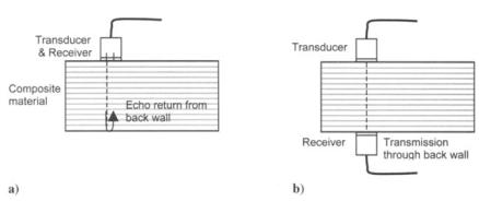
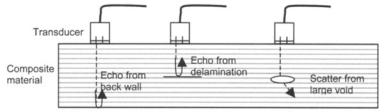
of robotics in conjunction with ultrasonics has led to the development of equipment such as the mobile automated ultrasonics system (MAUS) that permits rapid collection of data into a C-scan image.
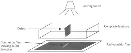
11.4.2.2 Radiography. X-rays, when passed through a structure, will be absorbed where the level of absorption is dependent on the physical density of the material. The differential absorption of materials allows the use of radiography for the inspection of particular defects in composite structures. The method of X-ray radiography as a NDI technique uses ionizing radiation through a structure (Fig. 11.7) where the level of absorption of the radiation is recorded by film on the opposing side of the structure. The level of contrast on the recording film is dependent on the level of radiation that has passed through the structure. The presence of varying local physical densities in the composite structure will show as a differential contrast on the film. Defects, which include foreign objects or debonds that have different physical densities to the resin and fiber of the composite, will be detected on film when oriented in the same plane as the transmitted beam. Defects such as delaminations and planar cracks are difficult to detect using radiography.
Penetrants are often used to enhance the contrast in the detection of planar defects. Penetrants used include zinc iodide, silver nitrate, trichloromethane, and diiodomethane. Choice of the penetrant is determined by the ease with which it can penetrate the delaminations and also with which it can be subsequently removed. Diiodomethane has the advantages of high opacity, ease of penetration, and ease of removal because it evaporates fairly quickly. However, it can cause skin bums.
The dangers of radiography have generally limited its use to inspection of parts removed from the aircraft. The development of real-time radiography using a localized computer controlled X-ray source and point detector has led to the wider use of the technique for in situ inspection.
11.4.3 Emerging Technologies
The development of alternative technologies for NDI of advanced composite structures has been driven by the need to dramatically reduce inspection times and increase the capability of detection for complex component design concepts. There are parallel efforts in NDI technologies for detection of defects of fabricated and in-service structures. The development of rapid and more efficient inspection technologies is being led by work in the fields of non-contact ultrasonics, real-time radiography, pulse thermography, digital shearography, and acoustic emission technologies.2° Work in these fields focuses on improving conventional NDI techniques, such as the replacement of the expensive and timeconsuming development of film in X-ray radiography using real-time imaging. The integration of the emerging NDI technologies with existing technologies
424 COMPOSITE MATERIALS FOR AIRCRAFT STRUCTURES
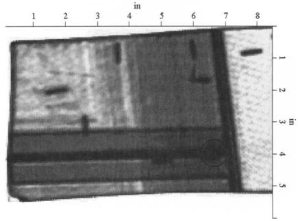
for inspection of a rib-stiffened composite box structure. Foreign object detection is shown from the inspection in the C-scan image.
Laser beam ultrasound is applicable to both electrically conducting and nonconducting materials with less disturbance in detection as a function of distance from part surface compared with the other non-contact techniques. Laser beam ultrasonics provides access in geometrically difficult-to-reach locations. In this method, short pulses are induced that cause rapid heating and expansion of the component surface. Laser detection of the reflected signals from the excited component is performed using an interferometer system. Fiedler et al.24 have shown the capability to generate a three-dimensional C-scan image of a curved part with discontinuities at various depths using laser ultrasonics. The main limiting factor of laser ultrasonics is the cost of the hardware. Buynak et al.25 inform of work that has demonstrated the relative ease for introducing perpendicular sound pulses on round surfaces using laser-based ultrasonic (LBU) technology, a task that is said by the same authors to be difficult to achieve with the traditional water jet systems.
A hybrid system that uses lasers to induce ultrasonic signals and electromagnetic acoustic transducers (EMAT) to measure the signals is reported. 26 This system overcomes the shortfalls of EMAT to induce ultrasonic signals when used alone.
11.4.3.2 Real-Time Radiography. Recent developments in real-time imaging technology have raised interest for expanding radiographic testing. Advances have been achieved in the areas of reverse geometry X-ray and microfocus X-ray microscopy.
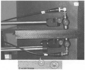
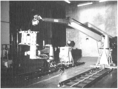
Real-time reverse X-ray systems that allow for portable and filmless inspection have been successfully used to detect in-service defects.27 In the reverse X-ray technique, a component is placed adjacent to the large scanning source and a point detector. A computer controls the X-ray tube and image construction. This technology is demonstrated for inspection of water entrapment and core crush in honeycomb core composite sandwich structures. The development of an integrated robotic X-ray system, as shown in Figure 11.9 demonstrates the potential implementation of an automated system for inspection in a production line and in the field for aerospace structures.
11.4.3.3 Thermography. In thermography, heat-sensing devices are used to measure temperature variations caused by differences in heat capacity or thermal conductivity in a structure. Thermography is well suited to detecting disbonds and delaminations.
The advantages of thermography are based on its non-contact application and high scanning rates. Passive thermography has been able to provide qualitative assessment of sub-surface defects, but has failed to match the quantitative capabilities of ultrasonics. This technique relies on heat diffusion driven by
QUALITY ASSURANCE |
425 |
Fig. 11.9 Robotic Digital X-ray probe. Courtesy Digiray Corporation.
ambient or process-related temperature fluctuations as the basis for detecting hidden structural faws.
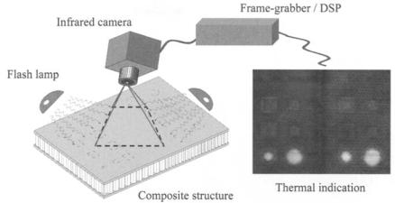
Developments in the field of pulse thermography have largely bridged the gap between the capabilities of ultrasonics and thermography. In pulsed tbermography, the surface of the sample is irradiated by a pulse of heat from a highpowered light source and monitored using an infrared sensor. Ideally, the heating should be highly uniform; however, it is often very difficult to achieve uniform heating (this being dependent on the shape and complexity of the component). The relative time and amplitude of the measured signal provides information about the depth and size of sub-surface defects. Areas located near defects will cool (heat diffuses away) at a different rate compared to defect-flee areas. Figure 11.10 shows the basic set-up of the thermography NDI method, where the application of a flash lamp heats the composite component and an infrared camera measures the temperature distribution in the component over time. The thermal image shows defective areas as lighter regions compared to dark for the surrounding material.
Limitations on thermography include optical reflecfivity, infrared emissivity and thermal diffusivity of the material. Thermography is most suited to large planar structures, or curved components with large radii of curvature. It is generally found that parts thicker than 12 mm are not practical for thermographic inspection. The low infrared emissivity, or high reflectance, of unprepared metal
QUALITY ASSURANCE |
427 |
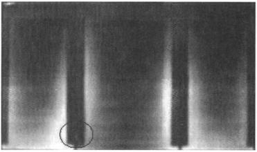
Fig. 11.11 Digital image from EchoTherm (thermal wave imaging) showing detection of interstitial void at skin to rib junction of a carbon/epoxy flap.
11.4.3.4 Optical Methods, Shearography, and Holography. In shearography a load is applied to a laminated structure that causes submerged defects to create surface strain discontinuities that are visually shown in a fringe pattern. The strain levels in the structure are measured by a digital interferometry system before and after a load is applied. Digital mapping of the component using image acquisition equipment generates fringe patterns permitting real-time inspection.
The basis of forming a shearographic fringe pattern is the application of a load to the structure. This is achieved through thermal and surface vacuum techniques. Davis2s demonstrated the capabilities of inspecting large areas of composite materials using thermal-stress shearography, whilst Bar-Cohen 2° demonstrated the use of thermal shearography on an aircraft. Figure 11.13 details the detection of a void at the junction of a rib to skin for a rib stiffened carbon/epoxy box structure. This image was generated by Steinbichler with the stationary Shearography System by using thermal excitation with an 8-mm objective.
Environmental disturbances, such as thermal currents and room vibrations are overcome in shearography by integrating the use of a common path optical arrangement and surface strain measurement. This system overcomes the problem of conventional holography. This technique can also detect very small defects through the formation of fringe patterns under stress. However, it is more sensitive to the mechanical stability of the structure.
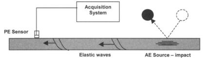
11.4.3.5 Acoustic Excitation and Sensing. The use of low frequency acoustic waves to excite a natural frequency response from a structure is the basic principle of the tap testing method. The tap test is the simple technique of using a