

AIRCRAFT APPLICATIONS AND DESIGN ISSUES |
447 |
measures must always be considered against the increased manufacturing and certification costs. Many designs have reverted to quasi isotropic lay-ups with the aim of reducing costs. The advantages of near quasi isotropic lay-ups for optimizing strength in mechanically fastened components are discussed in Chapter 9.
12,4 Design Considerations
12.4.1Choice of Materials
There are wide ranges of choice for both the reinforcement and the resin materials of the composite. This subject is covered more fully in Chapter 8. A summary is provided here. The most common combination for aerospace applications is an epoxy resin with carbon-fiber tape or fabric reinforcement, although BMI resins are used for high-temperature applications. In addition to these two thermosetting resins, there have been some successful applications of thermoplastic matrices such as PEEK, PEI, and PPS.Parts manufactured from thermoplastics are usually used in the smaller details due to the high forming pressures required that limit the size of part that can be formed in a conventional press. These can then be welded together to form larger components, a process not possible with thermosetting details. Thermoplastic resins were seen as attractive in the past due to their higher toughness and consequent improved resistance to impact damage. However, this advantage has been eroded somewhat by later-generation toughened epoxies. In addition, some thermoplastic resin matrices lose some toughness under some in-service conditions. PEI, in particular, has been shown to embrittle when exposed to prolonged high temperatures and furthermore is susceptible to attack from various chemicals occurring in standard aircraft fluids.
The costs of high-temperature thermoplastic materials are also considerably greater than those of competing thermosetting materials, as are the processing costs. As a result, thermoplastic systems have not been widely adopted in aerospace structures at this point.
Composite materials are usually supplied with the reinforcement preimpregnated with resin (pre-pregs) or, less frequently, separately. In the latter case, the resin is introduced after the dry reinforcement has been placed into a mold using some form of liquid-molding process. Details of these processes are covered in Chapter 5.
Because of the high cost of material qualification, aerospace companies are typically conservative when choosing materials and tend to select earlygeneration materials rather than those with improved properties to avoid additional material qualification costs. Unfortunately, there are no common materials data shared between users and, in many cases, a single material is qualified to similar requirements for several different customers. An attempt is
448 COMPOSITE MATERIALS FOR AIRCRAFT STRUCTURES
currently being made through MIL-HDBK 17 to deliver sets of properties for standard materials; however, this is as yet not comprehensive.
Carbon fiber is by far the most commonly used reinforcement material for aerospace composites. Boron fiber continues to be used for some older applications, particularly in the United States (e.g., the F-15); however, its high cost and the difficulty of processing into convenient reinforcement forms (e.g., woven and braided fabrics) and the difficulty of drilling or machining has very severely limited its application. Kevlar aramid fiber from DuPont had found some early applications, however, the limited compression strength of Kevlar composites and its tendency to absorb high proportions of moisture have led to a declining interest. It is now only mainly used for applications in which highenergy impact containment is required. The properties of composites based on these fibers are discussed in Chapter 8.
Reinforcements can be provided in a variety of woven or braid styles as well as in unidirectional plies. The latter provide the highest in-plane mechanical performance (stiffness and strength) due to the straightness and uniformity of the tows. Most weaves and all braids have "crimped" tows that reduce in-plane properties. This is particularly the case for compression strength that is very sensitive to fiber straightness. Nevertheless, braids provide a more convenient form for parts to be laid-up by hand.
Non-crimp weaves in which layers are stitched together into a carpet give properties somewhere between unidirectional and woven reinforcement, because the fibers are not held as straight as unidirectional tows. Non-crimps are highly drapeable and provide considerable advantage by reducing the number of individual plies to be laid. Currently they are not available as a pre-preg material and must be processed using liquid-molding techniques. Chapter 14 describes these forms in more detail.
12.4.2 General Guidelines
Composite structural design should not be attempted without a good working knowledge of the manufacturing limitations applying to composite materials. Generally, concurrent engineering is practiced whereby designers and manufacturing engineers work toward solutions that satisfy both design intent and production needs.
When specifying lay-ups (laminate ply stacks) and design details, some basic guidelines should be followed:
•Use balanced laminates to avoid warping
•Use manufacturing techniques that produce a minimum fiber content of 55% by volume;
•Use a minimum of 10% of plies in each of the principal directions (0°, 90 °,
_ 45 °) to provide a minimum acceptable strength in all directions
•Use a maximum of four adjacent plies in any one direction to avoid splitting on contraction from cure temperature or under load
AIRCRAFT APPLICATIONS AND DESIGN ISSUES |
449 |
• Place + 45 ° plies on the outside surfaces of shear panels to increase resistance to buckling
•Avoid highly directional laminates in regions around holes or notches because stress concentration factors are significantly higher in this ply lay-up
•Add ply of woven fiberglass barrier between carbon and aluminum alloy for galvanic protection
•Drop plies where required progressively in steps with at least 6 mm (0.25 in) landing to improve load redistribution
•Where possible, cover ply drops with a continuous ply to prevent end-of-ply delamination
•Maintain three-dimensional edge distance and four-dimensional pitch for mechanical fasteners to maximize bearing strength
•Where feasible, avoid honeycomb in favor of stiffened construction, because honeycomb is prone to moisture intrusion and is easily damaged
•Avoid manufacturing techniques that result in poor fiber alignment, because wavy fibers results in reduced stiffness and compression strength
•Minimize the number of joints by designing large components or sections
because joints reduce strength and increase weight and cost
•Allow for impact type damage (see later discussion); this may vary with risk (e.g., upper horizontal surfaces are at greatest risk).
•Exploit the non-isotropic properties of the material, where feasible.
•Ensure that the design reflects the limitations of the manufacturing processes to be used.
•Predict the failure loads and modes for comparison with test data
•Minimize or exclude the features that expose the notch-sensitivity of the material.
•Allow for degradation due to the environment.
•Provide for ready inspection of production defects.
•Allow for repair in the design.
•Predict and minimize, by design, out-of-plane loading.
•Include consideration of residual stresses in the cured laminate when calculating strength.
12.5Design of Carbon-Fiber-Based Components
12.5.1Static Strength
Carbon/epoxy in conventional ply configurations generally has significantly higher static strength than aluminum alloys. However, because of the brittle nature of the fibers, the composites are essentially elastic materials with very limited ability to redistribute loads at structural features such as fastener holes.7 The result is that they are quite notch-sensitive under static loading. As may be
450 COMPOSITE MATERIALS FOR AIRCRAFT STRUCTURES
expected, the higher the fiber modulus, the higher the notch-sensitivity, because the stiffer fibers have a reduced ability to accommodate high local strains. By contrast, aluminum alloys (and other structural metals) can redistribute stresses at mild stress concentrators by local yielding, so strength loss is often simply due to the reduction in net section.
The performance of laminates in the vicinity of holes and joints is highly affected by the lay-up. 8
Figure 12.8 shows the variation in stress concentration at the edge of a circular hole with ply lay-up. This shows that the estimated stress concentration factor increases with the proportion of fibers oriented in the load direction (e.g., if there are no + 45 ° fibers and 100% 0 ° fibers, Kt -- 8). Composites also have relatively low bearing strengths and quasi isotropic laminates are preferred in the area of bolted joints to ensure that there is at least some 0 ° fibers support the bearing loads regardless of load direction.
For these reasons, bonded joints are a better structural solution for composites; however, there are issues of maintenance and assurance of adequate bonded joint quality that must be taken into consideration. Also, bonded joints in thick section composites are complex and costly to manufacture. Joints are an extremely important design consideration, and Chapter 9 is devoted to this topic.
It is important to note that prior cyclic loading markedly reduces notch sensitivity of the composites by the formation of microcracks in the matrix and micro-delaminations between plies in regions of high initial stress concentration.
10
6
m
4
m
2 |
|
|
|
|
0 |
! |
I |
I |
I |
- 1 0 0 |
- 5 0 |
0 |
5 0 |
1 0 0 |
|
|
% ¢ 5 P l i e s - |
% 0 P l i e s |
|
Fig. 12.8 Stress concentration factors in laminates with varying proportions of onand off-axis plies. Based on Ref. 8.
AIRCRAFT APPLICATIONS AND DESIGN ISSUES |
453 |
More accurate results can be obtained from finite element analyses; however, whichever method is used to calculate induced stresses, the actual failure stresses need to be established through a calibrated test.
Joints, tapers, and ply drop-offs also give rise to significant through-thickness or peel stresses that can result in the formation of delaminations. The development of unexpected or higher than expected through-thickness stresses are major reasons for the formation of delaminations in large components. In many cases, these problems only arise when full-scale or large components are tested, or even in service, because they are often not detected at the coupon or structural element scale.
Detailed two-dimensional or three-dimensional finite-element analysis is used to determine the state of stress in complex full-scale components. However, modelling at the ply level can be prohibitively time-consuming and in any case may not correctly represent the "as fabricated" component.
12.5.3 Manufacturing Defects
The mechanical properties of composite structures are influenced by the presence of defects in the material arising from inconsistencies in manufacturing processes and controls. Typical defects include resin-rich or resin-dry areas, fiber misalignment, porosity, delaminations, and the inclusion of foreign materials, such as peel ply.
Most aircraft parts are inspected using automated equipment, set to scan the work at a discrete interval. A defect smaller than the interval may not be detected. On large parts, the interval is often set at approximately 6 ram, consequently defects smaller than 6 m m diameter may be missed on successive passes.
Other forms of defect can be inadvertently introduced at the assembly stage. Exit-side fiber damage and delamination can occur on drilled holes, for example, particularly if insufficient support is provided. The extensive use of composite materials in recent years and the development of drill bit technology has minimized these effects; however, it is important to ensure that test specimens used to obtain design allowables are representative of the accepted production practice. Handling damage and damage due to excessive force fit are also possible during the assembly stage.
Typical manufacturing defects must be allowed for in design, but allowance for impact damage as described in the next section will usually cover this requirement.
12.5.4 Impact Damage
Impact damage in composite airframe components is usually the main preoccupation of designers and airworthiness regulators. This is in part due to the extreme sensitivity of these materials to quite modest levels of impact, even when the damage is almost visually undetectable. Chapter 8 describes the mechanisms involved in impact damage and also provides more background on the influence of mechanical damage on residual strength.
454 COMPOSITE MATERIALS FOR AIRCRAFT STRUCTURES
Horizontal, upwardly facing surfaces are obviously the most prone to hail damage and should be designed to be at least resistant to impacts of around 1.7 J. The value represents the energy level generally accepted to represent extreme value in (1% probability of being exceeded) hail conditions. 1°
Surfaces exposed to maintenance work are generally designed to be tolerant to impacts resulting from tool drops.ll Figure 12.11 provides impact energy levels for a variety of different tool-drops, and Figure 12.12 indicates that monolithic laminates are more damage resistant than honeycomb structures. This is due to their increased compliance. However, if the impact occurs over a hard point such as above a stiffener or frame, the damage may be more severe, and if the joint is bonded, the formation of a disbond is possible.
12.5.4.1 BVID, VID, and Energy Cut-off Levels. The authorities have generally divided impact damage into two categories. The categories are
Impact |
Heighttool dropped |
|
|
|
||
energy |
(m) |
|
Impact energy (J) |
|||
(ft/Ib} . |
0.1 |
|
025 |
|
1.0 |
Z.S |
" ^ |
|
|
|
|
|
13.6 |
|
|
|
|
|
|
Blunt |
|
|
|
|
|
|
3 2 - p l y monolithic |
|
|
|
|
|
|
Sharp |
|
|
|
|
|
|
Blunt |
|
|
|
|
|
|
16 -- ply monolithic |
|
|
|
|
|
|
Sharp |
|
|
|
|
|
|
1.36 |
|
|
|
|
|
|
Blunt |
|
|
|
|
|
|
8 - ply monolithic |
|
|
|
|
|
|
Sharp |
|
|
|
|
|
|
8 -- ply honeycomb |
|
|
|
|
|
|
0.136 |
|
6 |
8 |
10 |
20 |
60 |
80 100 |
Height toobdrepped(in)
Fig. 12.11 Impact energy of dropped tools. Based on Ref. 11.
AIRCRAFT APPLICATIONS AND DESIGN ISSUES |
455 |
|||
|
Laminate thickness (ram) |
|
|
|
0.$ |
1.0 |
2.5 |
10 |
13.6 |
|
|
|
|
|
-I |
A |
I |
v |
|
1.36 |
6
I |
_E |
E |
|
m |
|
0.136
0,02 |
0,04 |
0,06 |
0.080.1 |
0.2 |
0.4 |
4 ply |
8 ply |
|
16 ply |
32 ply |
|
Laminate thickness (in.)
Fig. 12.12 Impact energy for incipient damage to carbon/epoxy laminates.
delineated by the ease of visibility (by the naked eye) of the damage rather than the energy of the impact: barely visible impact damage (BVID) and visible impact damage (VID). The definition of visibility is difficult to quantify because it depends on access, light conditions, and differences in human capability. Damage to an external surface could be expected to be more readily detectable; however, because it can be masked by paint. Quite often, backside damage fiber-break is more apparent than the corresponding impression on the impacted face. For airworthiness certification, the structure is expected to demonstrate an acceptable strength margin with BVID because this may not be detected for some time. It is not usually the surface condition that promotes a subsequent static failure, but more the associated underlying delaminations.
There is no current universally accepted definition of the term barely visible. Some authorities accept surface indentations of 1 mm; others give more
456 COMPOSITEMATERIALS FOR AIRCRAFT STRUCTURES
qualitative requirements, for example, that an indication be observable from a given distance (say, 1 m). It is invariably agreed that structures must be able to sustain ultimate load with this level of impact damage present in the structure and that it be able to withstand limit-load with damage that is clearly visible.
The USAF has accepted an upper threshold of impact energy of 100 ft lbs (around 135 J) as equal to a dropped tool b o x - - a once-in-a-lifetime expected event. Consequently, if the structure is capable of withstanding this without reduction in strength below an acceptable margin, the above criteria are not imposed. Figure 12.13 illustrates the situation. Other authorities such as the Joint Airworthiness Authority (JAA) have nominated 50 J as the energy cut-off.
12.5.5 Residual Strength
As noted, the compression strength of a composite laminate is substantially reduced subsequent to an impact event causing visible or even non-visible damage. For example, with laminates less than 3 m m thick, typical of control surface structures, compression strength can be reduced by more than 50% with BVID (Fig. 12.14). These reduction factors are often established at the coupon level through a standard compression-after-impact test, as discussed in Chapter 7. These tests generally involve impacting the test coupon with a specified energy level rather than specifying a degree of damage and were initially devised to provide a means by which different materials could be compared. They have, however, been widely adopted to establish allowable values for design.
Visibility Cut-Off
. 1 0 ~ - - - - |
|
t, . . |
|
|
t,L |
|
- |
- |
. . . / |
% - |
|
||
.=_" |
|
|
|
|
|
|
v |
|
|
|
|
tsl |
|
r- |
|
|
|
|
|
|
|
|
|
|
|
|
|
C~ .05 |
|
|
|
|
|
|
e.. |
|
|
|
|
|
|
E3 |
|
|
|
|
|
|
25 |
|
50 |
|
75 |
100 |
125 |
|
Impact |
Energy |
( f t - l b ) |
|
|
|
Fig. 12.13 Impac t d a m a g e assumptions. The symbol s tl, t2, etc. indicate increasing laminat e thickness. Adapte d f r o m Ref. 7.
AIRCRAFT APPLICATIONS AND DESIGN ISSUES |
457 |
1.0 |
|
~n¢- |
.7 |
i |
: |
|
|
|
|
|
|
|
|
|
|
|
"%% |
|
|
|
|||
|
|
|
-- |
|
|
|
|
|
||
|
.s -- |
|
|
|
"%"%"%~ |
|
|
|||
|
|
|
A |
|
De.lamination |
[ |
-,,.,.... |
|
||
|
|
|
• |
- - - - - - |
Impact |
Damage J |
Barely |
" i ~ - - |
~".':::LJ |
|
N |
.2 |
|
0 .......... |
Flawed |
Hole |
[ |
Visible |
|
U ' |
|
|
. . . |
. |
|
I |
|
|
Easily |
|||
|
.1 |
|
g - - - - - |
P'oroslzy |
J |
|
|
Visible |
||
|
|
|
I |
|
I |
|
I |
I |
|
|
|
|
|
|
|
|
!.5 |
||||
|
|
|
) |
.5 |
|
1.0 |
|
1.5 |
2.0 |
|
|
|
|
|
D a m a g e |
Dia . |
( i n ) |
o r |
P e r c e n t |
P o r o s i t y |
|
Fig. 12.14 Strength loss associated with impact damage.
In contrast, the residual strength after impact damage under tension is not usually considered as significant as other geometric characteristics, for example, fastener holes and notches, which are more critical. The case of the pressurized fuselage is an exception in which fail safety must be demonstrated in the presence of significant damage. 11 In such cases, the nature and size of damage is prescribed often following similar patterns to those known to occur in metal structures. Residual strength is usually then demonstrated by tests on full-scale subcomponents rather than by predictions from coupon data.
Horton et al. ~3provide more information on the subject of damage tolerance of composite laminates.
As discussed in Chapter 8, modelling tools for post-impact strength 14 are not sufficiently mature to be relied on, and certification is usually based on demonstrating (by test) that strain levels are sufficiently low and that failure will not occur even if damage is present. Thus residual strength tests, after impact (and other representative damage) are often performed at the various scale levels, 15including full scale after conclusion of the fatigue test program. Residual strength testing may follow some further representative cyclic loading to check for damage growth.
When quantifying residual strength after impact, it is preferable to work in terms of strain, because the stiffness of the laminate does not then need to be considered. The allowable ultimate compressive strain with BVID is not much less than the ultimate strength of an undamaged laminate in the region of a 6 - mm hole, and this latter allowable is sometimes used to cover both circumstances.
458COMPOSITE MATERIALS FOR AIRCRAFT STRUCTURES
12.5.6Damage Growth Prediction
As noted in Chapter 8, prediction of damage growth in composite laminates under cyclic loading is not straightforward. Consequently, design is generally based on a safe life with BVID damage assumed; in other words, there is no damage growth allowed under cyclic loading. Inspection intervals are set based on a demonstrated safe or no-growth life, suitably factored to allow for statistical variability.
12.5.7 Bird Strikes
Bird strikes are special cases, for example, in composite fan blades and leading edges, where it must be demonstrated that in the event of such an impact, safe continued flight and landing will not be impaired. As with metal structures (that must meet the same requirements) the issue is as much one of protection of systems behind the impact zone as of structural damage.
12.5.8 Damage Tolerance Improvements
Various methods can be considered to enhance the damage tolerance of composite materials. Some of these methods are discussed in the following paragraphs.
The ability of the composite structures to tolerate impact damage is largely dependent on the fiber and matrix properties. The increase in matrix material fracture toughness greatly enhances the damage tolerance of the composites. Published data 13 indicates that the residual compressive strength of composites after impact is directly proportional to the mode 1 strain energy release rate, Gzc. In tests on the same reinforcement with different resins, a matrix (resin) with twice the value of Gic showed a 50% improvement in residual strength after impact when compared with the base system.
The use of a tougher resin system or thermoplastic significantly improves damage tolerance. For example, Glc of a typical thermoplastic material is approximately 1050 J m -2 compared with 180 J m -2 for an un-toughened epoxy material.
There are two distinctly different issues in relation to the influence of matrix toughness on impact damage: resistance to damage and residual strength in the presence of damage. Generally, composites with tough matrices are resistant to delamination damage, as measured by delamination size for given impact conditions. However, for a given area of impact damage, both brittle and tough composites suffer about the same degradation in residual strength.
Fiber properties significantly influence damage tolerance: the stiffer the fiber, the less damage tolerant it will be. Composites with hybrid fiber construction [that is, where some percentage of the carbon fibers are replaced by fibers with higher elongation-to-failure ratios, such as E-glass or aramid (Kevlar)] have been
AIRCRAFT APPLICATIONS AND DESIGN ISSUES |
459 |
shown to have improved compression and tension strengths after impact. However, their basic undamaged properties, that is, strength and stiffness, are usually reduced.
Impacted laminates with higher percentages of plies oriented in the loading direction typically fail at lower strains than laminates with more off-axis plies. This is demonstrated in the case of open-hole strengths (Fig. 12.15). This shows typically how laminate strain-to-failure varies with lay-up and load orientation. Open-hole compression (OHC) and filled-hole tension (FHT) values are plotted against the percentages of bias plies in laminates. Similar data would be obtained from residual strength testing. This presentation is popular among several U.S. aerospace company design groups and is referred to as the angle-minus-loaded (AML) ply curve. It allows the establishment of relationships between lay-up and strength and enables projections and interpolations to be made, thus minimizing the testing that would otherwise be necessary. The horizontal axis is the percentage of bias (___45 ° plies) minus the percentage of on-axis (0° plies).
The designer needs to perform trade-off studies to optimize the lay-up; however, increasing percentages of softer plies in the load direction may improve the failure strain but reduce the load-carrying capability of the laminate. Even if failure occurs at a lower strain in a stiffer laminate, the higher modulus may result in higher stress-to-failure and thus higher load.
As noted earlier, laminated composites suffer from relatively poor throughthickness strength and stiffness. One of the more novel attempts to improve this is by through-thickness stitching of the fabric. Stitching is performed on a dry preform that is subsequently impregnated with resin using a liquid molding or
RTM process (see Chapter |
5). Stitching |
has |
been found to improve the |
|||
|
14,000 I |
|
|
|
|
|
|
i - |
- " " " - - ' - - " - ' ~ ' ~TENS- |
CTD |
|||
. ~ , |
12,000 |
|||||
¢ - |
J |
|
|
|
|
1 |
.~. |
|
|
~ |
|
|
|
•~ |
10,000 |
|
FlIT RTD |
|||
|
COMP E'I'N |
|||||
|
|
|
||||
F: |
8,000 |
|
OHC R'FD |
|||
oL |
|
|
|
|
|
|
t ~ |
|
/ |
|
|
|
|
a ~ |
6,ooo |
|
|
|
|
|
|
|
|
|
|
|
|
|
I |
|
|
|
|
|
|
4,000 |
0 |
50 |
|
1O0 |
|
|
-25 |
|
||||
|
|
Y',A.5 P l i e s |
- |
Y',O P l i e s |
|
|
Fig. 12.15 Effect of lay-up on failure strain.
460 COMPOSITE MATERIALS FOR AIRCRAFT STRUCTURES
delamination fracture toughness 16 and in some cases, also improves the impact resistance and tolerance. Some studies 17 have shown little improvement in damage resistance (measurement of damage after impact) of composites (laminates 1-3.5 mm thick) made from stitched carbon woven fabrics compared with non-stitched fabric laminates. Stitching was shown to improve impact damage tolerance; however, this was offset by the reduction of undamaged compressive strength of the stitched laminate. The investigation of failure modes has revealed that stitching may offer benefits where unstitched damaged material fails by sub-laminate buckling. Where the failure mode is predominantly transverse, stitching does not provide any benefit.
Other textile preforming techniques such as knitting, braiding, and threedimensional weaving also improve residual strength, however, again, their inplane properties degrade appreciably. Composites with three dimensional reinforcement are discussed in Chapter 14.
12.5.9 Elevated Temperature and Moisture Exposure
Probably the most critical environmental exposure condition for composite materials is the effect of elevated temperature. This is particularly the case for composites with thermoset matrices because these polymers absorb moisture when exposed to hot-humid conditions, further reducing elevated temperature properties. Chapter 8 covers more fully the mechanics of property degradation under elevated temperatures and moisture absorption. Thermoplastic matrices, by contrast, absorb little moisture; however, they soften at elevated temperatures and are often vulnerable to chemical attack (see again Chapter 8).
Exposure extremes vary depending on the intended operation conditions, but typically chosen values for subsonic aircraft are 70 °C and 85% relative humidity. Under these conditions, thermoset composites will absorb up to 1% by weight of water over time with a corresponding reduction of glass-transition temperature, Tg, of around 25 °C. The moisture plasticises the matrix-reducing stiffness at elevated temperatures.
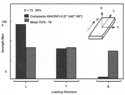
The effect of the matrix softening on the composite is a reduction in matrixdominated properties, such as shear or compression strength. Figure 12.16 shows a comparison of the marked effect of temperature on compression strength for a typical thermoset composite and for comparison an aluminum alloy, where the loss in strength is seen to be minimal.
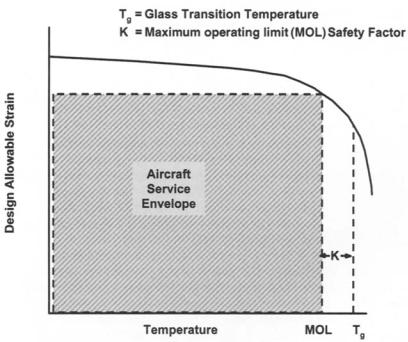
Because of the dramatic reduction in properties above Tg, the certification authorities specify a separation K between Tg and a maximum operating temperature of 25 °C (JAA) or 50 ° F MIL-HDBK 17 Figure 12.17.
It is normally required that property knockdowns for design are established after the material has become moisture saturated under the extreme operating conditions. Because of the slow absorption rate, particularly noticeable in thick specimens, conditioning can take many months. Recent efforts are investigating the possibility of testing a dry specimen under a higher temperature to
|
AIRCRAFT APPLICATIONS AND DESIGN ISSUES |
|
461 |
|||
1.0 |
|
|
|
|
|
|
0.8 |
|
|
|
|
|
|
0.6 |
|
|
|
|
|
|
ko |
|
|
|
|
|
|
0.4 |
|
|
|
|
|
|
0.2 |
= 2 G P a |
|
i |
( |
o |
/3501-6) |
|
|
|
! |
1.2~ |
Moisture |
|
|
I |
I |
~ |
|
|
I |
|
50 |
100 |
|
|
|
150 |
|
T e m p e r a t u r e |
( ° C ) |
|
|
|
|
Fig. 12.16 |
Influence of temperature on compression |
strength |
of |
carbon/epoxy |
||
laminate. Adapted from Ref. 7. |
|
|
|
|
|
|
compensate for the lack of moisture, however the validity of such an approach has not yet been proven.
Fiber-dominated properties, for example, tension strength, are not adversely affected by resin plasticization. In fact, the tensile properties of woven (crimped) materials are increased. However, fiber-dominated properties are adversely affected by embrittlement arising from exposure to very low temperatures. A typical tensile strength reduction for a carbon-fiber-reinforced plastic material exposed to temperatures existing at very high attitude is around 20 - 25% .
12.5.10Lightning Effects
Carbon-fiber reinforced plastic composites are conducting materials, but because they have a significantly lower conductivity than aluminum alloys, the effect of direct lightning strikes is an issue of concem to airworthiness authorities. The severity of the electrical charge profiles 18'19depend on whether the structure is in a zone of direct initial attachment, a "swept" zone of repeated attachments or in an area through which the current is being conducted. Survivability of structures in the direct attachment or swept zones will require some form of protection. The most effective methods involve the incorporation of a metal, bronze, copper, or aluminum, mesh, or foil co-bonded on the outer skin of the laminate. This mesh must make direct contact with the carbon-fiber material to be effective. Particular attention must be paid to the electrical bonding (connectivity) of the panel to the adjacent structure. Current will gravitate to points of high conductivity such as mechanical fasteners, and good electrical contact between the fastener, protective mesh, and subsequent electrical
AIRCRAFT APPLICATIONS AND DESIGN ISSUES |
463 |
method will dictate the details of the laminate and qualification testing that will subsequently be required to validate or show that the various assumptions that have been made are adequately conservative.
A common assumption when analyzing rods and beams is that plane sections remain plane. In this case, for the condition of "no bending," strain is constant through the thickness, whereas stress varies from ply to ply depending on the modulus and orientation of each ply. For convenience, this leads to the use of strain analyses rather than stress analyses. Similarly, it is assumed that strains vary linearly through the thickness of plates in bending, an assumption that is reasonable, particularly for thin-shell aircraft structures. It enables the laminate to be treated as a homogeneous material and for the strains in the 1-1, 2-2, and 1-2 directions to be calculated (see Chapter 6). The simplest method of the subsequent strength prediction then introduces the assumption that the strength of any laminate is limited to a value pertaining when the strain in any one ply in the laminate exceeds a prescribed value. This is known as the first-ply failure method. Some variations of this method set the limiting value as a principal strain or maximum directional strain, whereas others base the ply failure on more complex relationships of bi-axial strain--see for example the Tsai-Hill criterion (also see Chapter 6). There has, long been debate over which of these criteria provide the best estimates of strength, however, this is likely to depend on the particular materials under consideration, the relative strains-to-failure of the reinforcement and matrix systems, and the loading. For many laminates, the maximum directional strain criterion is often used. Failure strain values are established from coupon tests on standard laminates in which the plies are orientated in the direction of the (uniaxial) load.
The more rigorous approach recognizes that the laminate strength is influenced by lay-up and stacking sequence. These influences are not altogether well understood. Some credit is given to differences in residual stresses remaining in the laminate after cure; however, predictions of residual stress and subsequent laminate strength do not always provide improved estimates. As it stands currently (if these effects are to be included) laminate capacities have to be established by tests on individual laminates. The difficulty with this approach is that there are often many different laminates in a single structure, and there may be several different load vectors applied. This means that each laminate may need to be tested under each loading combination, and to satisfy issues of variability, a number of coupons are required to establish each data point, leading to hundreds, and in some cases thousands, of tests. The larger companies have established such databases over long periods of time, and this explains the reluctance of many to change systems even when improved or cheaper materials become available.
The integration of testing into the overall design process is illustrated in Figure 12.18. (Note here the emphasis on trade-off studies that will establish an appropriate balance between cost and weight. These are essential if cost-effective design solutions are to result.)
|
AIRCRAFT APPLICATIONS AND DESIGN ISSUES |
465 |
||
1.0 ~ |
|
|
AS 3501-6 |
|
0.80.9- |
~ , ~ |
|
RT/Ambient |
|
0 7 |
|
As Damaged |
~ |
--~ |
kdc 0.6 |
+ Spectrum Fatig |
, . |
w = 7" mm |
|
0.5 |
|
|
|
|
0.4.---- |
|
|
|
|
0.3' |
|
|
|
|
0.2 |
|
|
|
|
0.1 |
|
|
|
|
I |
I |
I |
I |
0 |
25 |
50 |
|
|
Damage Diameter d (mm) |
|
|
Fig. 12.20 Knockdown factor compression residual strength for impact damaged carbon/epoxy laminate after spectrum loading. Adapted from Ref. 7.
ko: temperature; kth, keh: open-hole tension and compression, respectively; kuc, kdt: impact damage tension and compression, respectively.
The values to be attributed to these knockdowns will vary with material and lay-up, and the values provided in these figures are only a guide.
It is a common practice to multiply these factors to obtain combined affects. For example, in the case of a combined factor for a specimen with a 6.25 m m open hole, the compression allowable under hot/wet conditions would be:
kchO = kch × ko = 0.65 × 0.85 = 0.55
Combining these factors in this manner tends to be highly conservative and for this reason is generally acceptable to airworthiness authorities.
Typical maximum strain values used in design are between 4000 - 5000 microstrain (strain x 106) in tension and 3000 - 4000 microstrain compression. These values take into account combinations of environmental conditioning and impact damage or other stress concentrations.
In addition to point strain, other potential failure modes such as local and general instability (buckling), interlaminar strain, and bearing require consideration. Local instabilities by themselves may not be limits to load capacity; however, their presence will elevate point strains due to local bending and ultimately the maximum allowable ply strains may be exceeded. Non-linear finite element analyses are required for investigation of these conditions. Chapters 6 and 16 provide further information on this topic.
In the case of carbon/epoxy laminates, if the static strength has been established with due account for knockdown effects and the usual ultimate/limit load factor, it is not usually necessary to consider fatigue because the design limit