

Biomolecular Sensing Processing and Analysis - Rashid Bashir and Steve Wereley
.pdf176 JOEL VOLDMAN
TABLE 8.2. Comparison of advantages and disadvantages of p-DEP and n-DEP approaches to trapping cells.
p-DEP |
n-DEP |
|
|
Must use low conductivity artificial media (−) |
Can use saline or other high-salt buffers (+) |
CM factor can go to +1 (+) |
CM factor can go to −0.5 (−) |
Less heating (+) |
More heating (−) |
Typically easier to trap by pulling (+) |
Typically harder to trap by pushing (−) |
Traps usually get stronger as V increases (+) |
Traps often do not get stronger with increasing V (−) |
Cells stick to or can be damaged by electrodes (−) |
Cells are physically removed from electrodes (+) |
Cells go to maximum electric field (−) |
Cells go to minimum electric field (+) |
8.4.1.1.Interdigitated Electrodes Numerous approximate and exact analytical solutions exist for the interdigitated electrode geometry (Figure 8.5A), using techniques as varied as conformal mapping [23, 82], Green’s function [10, 86], and Fourier series [33, 61]. Recently, an elegant exact closed-form solution was derived [8]. Numerical solutions are also plentiful [28].
While the interdigitated electrode geometry has found much use in DEP separations, it does not make a good trap for a few reasons. First, the long extent of the electrodes in one direction creates an essentially 2-D field geometry and thus no trapping is possible along the length of the electrodes. Further, the spatial variations in the electric field—which create the DEP force—decrease exponentially away from the electrode surface. After about one electrode’s worth of distance away from the susbtrate, the field is mostly uniform at a given height, and thus DEP trapping against fluid flows or other perpendicular forces cannot occur. Increasing the field to attempt to circumvent this only pushes the particle farther away from the electrodes, a self-defeating strategy; like the planar quadrupole [83], this trap is actually strongest at lower voltages, when the particle is on the substrate.
8.4.1.2.Quadrupole Electrodes Quadrupole electrodes are four electrodes with alternating voltage polarities applied to every other electrode (Figure 8.5B). The field for four point charges can be easily calculated by superposition, but relating the charge to voltage (via the capacitance) is difficult in general and must be done numerically.
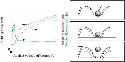
Planar quadrupoles can create rudimentary particle traps (Figure 8.5B), and can trap single particles down to 100’s of nm [40]. Using n-DEP, they provide in-plane particle confinement, and can provide three-dimensional confinement if the particle is denser than the suspending medium. As with interdigitated electrodes, however, these traps suffer from the drawback that increasing the field only pushes the particle farther out of the trap and does not necessarily increase confinement. We showed this in 2001 with measurements of the strength of these traps [83]. Unexpectedly, the traps are strongest at an intermediate voltage, just before the particle is about to be levitated (Figure 8.6).
A variant of the quadrupole electrodes is the polynomial electrode geometry (Figure 8.5C), introduced by Huang and Pethig in 1991 [36]. By placing the electrode edges at the equipotentials of the applied field, it is possible to analytically specify the field between the electrodes. One caveat of this approach is that it solves the 2-D Laplace equation, which is not strictly correct for the actual 3-D geometry; thus, the electric field is at best only truly specified right at the electrode surface, and not in all of space.
DIELECTROPHORETIC TRAPS FOR CELL MANIPULATION |
177 |
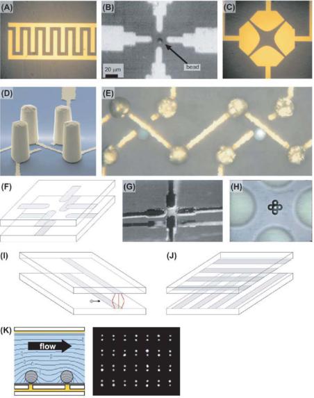
FIGURE 8.5. DEP trapping structures. (A) Interdigitated electrodes. (B) A planar quadrupole, showing a bead in the center. (C) Quadrupolar polynomial electrodes. (D) A 3-D view of an extruded quadrupole trap, showing the four gold post electrode electrodes and the gold wiring on the substrate. (E) A top-down image of two extruded quadrupole traps showing living trapped HL-60 cells in liquid. (F–H) Schematic (F), stereo image (G), and topdown view (H) of the oppose ocotpole, showing beads trapped at the center. (I) Schematic of the strip electrodes, showing the non-uniform electric field between them that creates an n-DEP force wall to incoming particles.
(J) Schematic of the crossed-electrode p-DEP structure of Suehiro and Pethig [77]. (K) Side view schematic of Gray et al.’s p-DEP trap, showing the bottom point electrodes and the top plate, along with a top-down image of endothelial cells positioned at an array of traps.
178 |
JOEL VOLDMAN |
0.8 |
|
|
|
40 |
0.6 |
|
|
|
30 |
0.4 |
|
|
|
20 |
0.2 |
|
|
|
10 |
|
|
|
|
0 |
1 |
2 |
3 |
4 |
5 |
(A) pre-levitation
drag |
|
|
bead |
|
|
|
|
|
|
forces |
|
|
DEP forces |
|
|
|
|
||
|
|
|
gravitational force |
|
|
|
|
|
|
|
|
|
substrate |
|
(B) rapid ascent
(C) saturation
FIGURE 8.6. Behavior of planar quadrupole trap at different voltages, showing the measured (o) and simulated (—) release flowrate, the holding force (· · ·), and the height of the particle when it is released (- - -). (A) Pre-levitation. At very low voltages, the z-directed DEP force cannot overcome the gravitation force, and the bead is not levitated; (B) Rapid ascent. At a certain voltage the bead will just become levitated and the holding characteristics will peak; (C) Saturation. At high voltages, the increase in holding force is balanced by the increased particle levitation height, resulting in a flat release flowrate profile.
One way to avoid this behavior is to extend the electrodes into the third-dimension, creating extruded quadrupole traps (Figure 8.5D–E, [84, 85]). These traps, while much more difficult to make, are orders of magnitude stronger than the planar quadrupole traps, and can successfully hold single cells against significant liquid flows. These electrode geometries are sufficiently complicated that only numerical simulation can derive the correct field solution.
8.4.1.3.Octopole Electrodes Another way to increase the strength of quadrupole electrode traps is to put another quadrupole on the chamber ceiling to provide further particle confinement (Figure 8.5F–H). These opposed octopole traps are significantly stronger than planar quadrupoles, and are routinely used for single-particle trapping [69, 71]. They are much simpler to fabricate than the extruded quadrupoles, but are more complex to align and package.
8.4.1.4.Strip Electrodes Strip electrodes are simply two electrodes opposed from one-another, with one on the substrate and one on the chamber ceiling (Figure 8.5I). Introduced by Fiedler et al. in 1998, these have been used to create n-DEP “barriers” to herd particles [14]. The solution to this geometry has been analytically solved using conformal mapping [72]. As with the interdigitated electrodes, strip electrodes are of limited use for particle trapping because they only provide one dimension of confinement.
8.4.1.5.Other Electrode Structures Several other microscale trapping structures have been introduced. Some, like the castellated electrodes [22, 59] or round electrodes [34], which have been successfully used for particle separation, are not well-suited for trapping particles because of their planar format; they suffer the same drawbacks as the interdigitated and planar quadrupoles.
DIELECTROPHORETIC TRAPS FOR CELL MANIPULATION |
179 |
Recently, a team in Europe has been developing an active n-DEP-based trapping array [56]. Essentially, their device consists of a two-dimensional array of square electrodes and a conductive lid. The key is that incorporating CMOS logic (analog switches and memory) allows each square electrode to be connected to in-phase or out-of-phase AC voltage in a programmable fashion. By putting a center square at +V and the surrounding squares at −V, they can create an in-plane trap. Further putting the chamber top at +V closes the cage, giving 3-D confinement. The incorporation of CMOS further means that very few leads are required to control an indefinite number of sites, creating a readily scalable technology. Using this trap geometry, they have successfully manipulated both beads and cells, although moving cells from one site to another is currently quite slow ( sec).
8.4.2. p-DEP Trap Geometries
p-DEP traps, while easier to create, have seen less use, probably because the required low-conductivity media can perturb cell physiology (at least for mammalian cells) and because of concerns about electrode-cell interactions. As stated earlier, obtaining p-DEP with mammalian cells requires low-conductivity buffer, and this can create biological artifacts in the system. Nonetheless, several geometries do exist.
An early p-DEP-based trapping system was described by Suehiro and Pethig (Figure 8.5J, [77]). This used a set of parallel individually addressable electrodes on one substrate and another set of electrodes on the bottom substrate that were rotated 90◦. By actuating one electrode on top and bottom, they could create a localized field maximum that could be moved around, allowing cell manipulation.
Another example is a concentric ring levitator that uses feedback-controlled p-DEP to actually trap particles away from electrodes [66]. In an air environment, they can levitate drops of water containing cells by pulling up against gravity with an upper electrode, feeding back the vertical position of the droplet to maintain a constant height.
Recently Gray et al. created a geometry consisting of a uniform top plate and electrode points on the substrate to create the field concentrations (Figure 8.5K, [27]). They were able to pattern cells onto the stubs using p-DEP. Importantly, experiments showed that the lowconductivity buffer did not affect the gross physiology of the cells at reasonable voltages. Finally, Chou et al. used geometric constrictions in an insulator to create field maxima in a conductivity-dominated system [9]. These maxima were used to trap DNA.
8.4.3. Lessons for DEP Trap Design
The preceding discussion raises some important points for DEP trap design. First, the choice of whether to trap via p-DEP or n-DEP is a system-level partitioning problem. For instance, if one absolutely requires use in saline, then n-DEP must be used. If, however, minimizing temperature rises is most important, then p-DEP may be better, as the lowconductivity media will reduce temperature rises. The decision may also be affected by fabrication facilities, etc.
In general, p-DEP traps are easier to create than n-DEP traps, because it is easier to hold onto a particle by attracting it than repelling it. The tradeoff is that p-DEP requires artificial media for use with mammalian cells. Nonetheless, the key for effective p-DEP is the creation of isolated field maxima. Because the particles are pulled into the field, p-DEP traps always trap stronger at higher voltages.
180 |
JOEL VOLDMAN |
Creating effective n-DEP traps is more difficult, and requires some sort of threedimensional confinement. This is difficult (though not impossible) to do with planar electrode structures, because the +z-component of the DEP force scales with voltage just as much as the in-plane components. This fundamentally pushes the particle away from the trap when one increases the voltage, drastically limiting trap strength. Any planar electrode structure, including the planar quadrupoles and interdigitated electrodes described above fail this test and therefore make a poor n-DEP trap. The two extant structures that exhibit strong trapping create three-dimensional trapping by removing the net +z-directed DEP force. Both the extruded quadrupole and opposed octopole structures do this by creating a structure that cancels out z-directed DEP forces at the trap center, enabling one to increase voltage—and thus trap strength—without pushing the particle farther away.
8.5. QUANTITATING TRAP CHARACTERISTICS
In order to assess whether a quantitative design is successful, one needs some quantitative validation of the fields and forces in DEP traps. Given that the complete DEP theory is known and that the properties of at least some particles are known, it should be possible to quantitate trap parameters. Those that are of interest include trap strength, field strength, and the spatial extents of the trap.
Measuring traps requires a quantitative readout. This typically takes the form of a test particle (or particles), whose location or motion can be measured and then matched against some prediction. Quantitative matching gives confidence in the validity of a particular modeling technique, thus allowing predictive design of new traps.
Starting in the 1970’s, Tom Jones and colleagues explored DEP levitation in macroscopic electrode systems [47–49, 53]. Using both stable n-DEP traps and p-DEP traps with feedback control, they could measure levitation heights of different particles under various conditions. Knowledge of the gravitation force on the particle could then be used to as a probe of the equally opposing DEP forces at equilibrium.
Levitation measurements have continued to the present day, but now applied to microfabricated electrode structures, such as levitation height measurements of beads in planar quadrupoles [15, 25, 32], or on top of interdigitated electrodes [37, 58]. In all these measurements, errors arise because of the finite depth of focus of the microscope objective and because it is difficult to consistently focus on the center of the particle. The boundary between levitation and the particle sitting on the ground is a “sharp” event and is usually easier to measure and correlate to predictions than absolute particle height [25].
Wonderful pioneering work in quantitating the shapes of the fields was reported by the group in Germany in the 1992 and 1993 when they introduced their planar quadrupole [15] and opposed octopole [69] trap geometries. In the latter paper, the authors trapped 10’s of beads that were much smaller than the trap size. The beads packed themselves to minimize their overall energy, in the process creating surfaces that reflected the force distribution in the trap. By comparing the experimental and predicted surfaces, they could validate their modeling.
An early velocity-measurement approach was described X.-B. Wang et al., who used spiral electrodes and measured radial velocity and levitation height of breast cancer cells as they varied frequency, particle radius, and medium conductivity [89]. They then matched
DIELECTROPHORETIC TRAPS FOR CELL MANIPULATION |
181 |
the data to DEP theory, using fitting parameters to account for unknown material properties, and obtained good agreement. These researchers performed similar analyses using erythroleukemia cells in interdigitated electrode geometries, again obtaining good fits of the data to the theory [88].
Another approach that compares drag force to DEP force is described by Tsukahara et al., where they measured the velocity as a particle moved toward or away from the minimum in a planar quadrupole polynomial electrode [80]. If the electric field and particle properties are known, it should be possible to relate the measured velocity to predictions, although, as described earlier, the use of Stokes drag introduces errors when the particle is near the wall and the forces they calculated for their polynomial electrodes are only valid at the electrode symmetry plane. This was reflected in the use of a fitting parameter to match predictions with experiment, although in principle absolute prediction should be possible.
The German team that initially introduced the idea of opposed electrodes on both the bottom and top of the chamber have continued their explorations into this geometry with great success. They have attempted to quantify the strength of their traps in two different ways. In the first approach, they measure the maximum flowrate against which a trap can hold a particle. Because of the symmetry of their traps, the particles are always along the midline of the flow, and by approximating the drag force on the particle with the Stokes drag (Eqn (8.15)) they can measure the strength of the trap in piconewtons [13, 62, 72]. Because they can calculate the electric fields and thus DEP forces, they have even been able to absolutely correlate predictions to experiment [72]. With such measurements they have determined that their opposed electrode devices can generate 20pN of force on 14.9-µm diameter beads [62].
The other approach that these researchers have taken to measuring trap strength is to combine DEP octopole traps with optical tweezers [2]. If the strength of one of the trapping techniques is known then it can be used to calibrate the other. In one approach, this was done by using optical tweezers to displace a bead from equilibrium in a DEP trap, then measuring the voltage needed to make that bead move back to center [18]. They used this approach to measure the strength of the optical tweezers by determining the DEP force on the particle at that position at the escape voltage. In principle, one could use this to calibrate the trap if the optical tweezer force constant was known.
In the other approach, at a given voltage and optical power, they measured the maximum that the bead could be displaced from the DEP minimum before springing back [70]. This is very similar to the prior approach, although it also allows one to generate a forcedisplacement characteristic for the DEP trap, mapping out the potential energy well.
A clever and conceptually similar approach was tried by Hughes and Morgan with a planar quadrupole [41], although in this case the unknown was the thrust exerted by E. coli bacteria. By measuring the maximum point that the bacteria could be displaced from the DEP trap minimum, they could back out the bacterial thrust if the DEP force characteristic in the trap was known. They achieved good agreement between predictions and modeling, at least at lower voltages.
For much smaller particles, where statistics are important, Chou et al. captured DNA in electrodeless p-DEP traps. They used the spatial distribution of the bacteria to measure the strength of the traps [9]. They measured the width of the fluorescence intensity distribution of labeled DNA in the trap, and assuming that the fluorescence intensity was linearly related to concentration, could extract the force of the trap by equating the “Brownian” diffusive
182 |
JOEL VOLDMAN |
force to the DEP force. The only unknown in this approach, besides the assumptions of linearity, was the temperature, which could easily be measured.
In our lab we have been interested in novel trap geometries to enable novel trapping functionalities. One significant aim has been to create DEP traps for single cells that are strong enough to hold against significant liquid flows, such that cells and reagents can be transported on and off the chips within reasonable time periods ( min). Our approach to measuring trap strength is similar to the one described above, where the fluid velocity necessary to break through a barrier is correlated to a barrier force [13, 62, 72]. This approach is also similar to those undertaken by the optical tweezer community, who calibrate their tweezers by measuring the escape velocity of trapped particles at various laser powers.
We have chosen to generalize this approach to allow for particles that may be near surfaces where Stokes drag is not strictly correct, where multipolar DEP forces may be important, and where electrode geometries may be complex [83]. In our initial validation of this approach, we were able to make absolute prediction of trap strength, as measured by the minimum volumetric flowrate needed for the particle to escape the trap. This volumetric flowrate can be related to a linear flowrate and then to a drag force using the analytical solutions for the drag on a stationary particle near a wall.
Our validation explained the non-intuitive trapping behavior of planar quadrupole traps (Figure 8.6), giving absolute agreement—to within 30%—between modeling and experiment with no fitting parameters [83]. We then extended this modeling to design a new, high-force trap created from extruded electrodes that could hold 13.2-µm beads with 95 pN of force at 2 V, and HL-60 cells with 60 pN of force at the same voltage [84, 85]. Again, we could make absolute predictions and verify them with experiments. We continue to extend this approach to design traps for different applications.
8.6. CONCLUSIONS
In conclusion, DEP traps, when properly confined, can be used to confine cells, acting as electrical tweezers. In this fashion cells can be positioned and manipulated in ways not achievable using other techniques, due to the dynamic nature of electric fields and the ability to shape the electrodes that create them.
Achieving a useful DEP system for manipulating cells requires an understanding of the forces present in these systems and an ability to model their interactions so as to predict the operating system conditions and whether they are compatible with cell health, etc. I have presented one approach to achieving these goals that employs quantitative modeling of these systems, along with examples of others who have sought to quantitate the performance of their systems.
8.7. ACKNOWLEDGEMENTS
The author wishes to thank Tom Jones for useful discussions and Thomas Schnelle for the some of the images in Figure 8.4. The author also wishes to acknowledge support from NIH, NSF, Draper Laboratories, and MIT for this work.
DIELECTROPHORETIC TRAPS FOR CELL MANIPULATION |
183 |
REFERENCES
[1]S. Archer, T.T. Li, A.T. Evans, S.T. Britland, and H. Morgan. Cell reactions to dielectrophoretic manipulation.
Biochem. Biophys. Res. Commun., 257:687–698, 1999.
[2]A. Ashkin. Optical trapping and manipulation of neutral particles using lasers. Proc. Natl. Acad. Sci. U.S.A., 94:4853–4860, 1997.
[3]A. Blake. Handbook of Mechanics, Materials, and Structures. Wiley, New York, pp. 710, 1985.
[4]R.H. Burdon. Heat-shock and the heat-shock proteins. Biochem. J., 240:313–324, 1986.
[5]S.W. Carper, J.J. Duffy, and E.W. Gerner. Heat-shock proteins in thermotolerance and other cellular processes. Cancer Res., 47:5249–5255, 1987.
[6]A. Castellanos, A. Ramos, A. Gonzalez, F. Morgan, and N. Green. AC Electric-Field-Induced Fluid Flow in Microelectrode Structures: Scaling Laws. Presented at Proceedings of 14th International Conference on Dielectric Liquids, Graz, Austria, 7–12 July 2002.
[7]W.A. Catterall. Structure and function of voltage-gated ion channels. Ann. Rev. Biochem., 64:493–531, 1995.
[8]D.E. Chang, S. Loire, and I. Mezic. Closed-form solutions in the electrical field analysis for dielectrophoretic and travelling wave inter-digitated electrode arrays. J. Phys. D: Appl. Phys., 36:3073–3078, 2003.
[9]C.F. Chou, J.O. Tegenfeldt, O. Bakajin, S.S. Chan, E.C. Cox, N. Darnton, T. Duke, and R.H. Austin. Electrodeless dielectrophoresis of singleand double-stranded DNA. Biophys. J., 83:2170–2179, 2002.
[10]D.S. Clague and E.K. Wheeler. Dielectrophoretic manipulation of macromolecules: The electric field. Phys. Rev. E, 64:026605–8, 2001.
[11]E.A. Craig. The heat shock response. CRC Crit. Rev. Biochem., 18:239–280, 1985.
[12]A. Docoslis, N. Kalogerakis, and L.A. Behie. Dielectrophoretic forces can be safely used to retain viable cells in perfusion cultures of animal cells. Cytotechnology, 30:133–142, 1999.
[13]M. Durr, J. Kentsch, T. Muller, T. Schnelle, and M. Stelzle. Microdevices for manipulation and accumulation of microand nanoparticles by dielectrophoresis. Electrophoresis, 24:722–731, 2003.
[14]S. Fiedler, S.G. Shirley, T. Schnelle, and G. Fuhr. Dielectrophoretic sorting of particles and cells in a microsystem. Anal. Chem., 70:1909–1915, 1998.
[15]G. Fuhr, W.M. Arnold, R. Hagedorn, T. Muller, W. Benecke, B. Wagner, and U. Zimmermann. Levitation, holding, and rotation of cells within traps made by high-frequency fields. Biochimi. Et Biophys. Acta, 1108:215–223, 1992a.
[16]G. Fuhr, H. Glasser, T. Muller, and T. Schnelle. Cell manipulation and cultivation under AC electricfield influence in highly conductive culture media. Biochimi. Et Biophys. Acta-Gen. Sub., 1201:353–360, 1994.
[17]G. Fuhr, R. Hagedorn, T. Muller, W. Benecke, and B.Wagner. Microfabricated electrohydrodynamic (EHD) pumps for liquids of higher conductivity. J. Microelectromech. Sys., 1:141–146, 1992b.
[18]G. Fuhr, T. Schnelle, T. Muller, H. Hitzler, S. Monajembashi, and K.O. Greulich. Force measurements of optical tweezers in electro-optical cages. Appl. Phys. A-Mater. Sci. Process., 67:385–390, 1998.
[19]P. Ganatos, R. Pfeffer, and S. Weinbaum. A strong interaction theory for the creeping motion of a sphere between plane parallel boundaries. Part 2. Parallel motion. J. Fluid Mech., 99:755–783, 1980.
[20]P.R.C. Gascoyne and J. Vykoukal. Particle separation by dielectrophoresis. Electrophoresis, 23:1973–1983, 2002.
[21]P.R.C. Gascoyne, X.-B. Wang, Y. Huang, and F.F. Becker. Dielectrophoretic separation of cancer cells from blood. IEEE Trans. Ind. Appl., 33:670–678, 1997.
[22]P.R.C. Gascoyne, H. Ying, R. Pethig, J. Vykoukal, and F.F. Becker. Dielectrophoretic separation of mammalian cells studied by computerized image analysis. Measure. Sci. Technol., 3:439–445, 1992.
[23]W.J. Gibbs. Conformal Transformations in Electrical Engineering. Chapman & Hall, London, pp. 219, 1958.
[24]H. Glasser and G. Fuhr. Cultivation of cells under strong ac-electric field - differentiation between heating and trans-membrane potential effects. Bioelectrochem. Bioenerget., 47:301–310, 1998.
[25]H. Glasser, T. Schnelle, T. Muller, and G. Fuhr. Electric field calibration in micro-electrode chambers by temperature measurements. Thermochimi. Acta, 333:183–190, 1999.
[26]A.J. Goldman, R.G. Cox, and H. Brenner. Slow viscous motion of a sphere parallel to a plane wall - II Couette flow. Chem. Eng. Sci., 22:653–660, 1967.
[27]D.S. Gray, J.L. Tan, J. Voldman, and C.S. Chen. Dielectrophoretic registration of living cells to a microelectrode array. Biosens. Bioelectron., 19:1765–1774, 2004.
184 |
JOEL VOLDMAN |
[28]N.G. Green, A. Ramos, and H. Morgan. Numerical solution of the dielectrophoretic and travelling wave forces for interdigitated electrode arrays using the finite element method. J. Electrostat., 56:235–254, 2002.
[29]A.W. Griffith and J.M. Cooper. Single-cell measurements of human neutrophil activation using electrorotation. Anal. Chem., 70:2607–2612, 1998.
[30]A.J. Grodzinsky and M.L. Yarmush. Electrokinetic separations. In G. Stephanopoulus (ed.), Bioprocessing, Weinheim, Germany; New York, VCH, pp. 680–693, 1991.
[31]C. Grosse and H.P. Schwan. Cellular membrane potentials induced by alternating fields. Biophys. J., 63:1632– 1642, 1992.
[32]L.F. Hartley, K. Kaler, and R. Paul. Quadrupole levitation of microscopic dielectric particles. J. Electrostat., 46:233–246, 1999.
[33]Z. He. Potential distribution within semiconductor detectors using coplanar electrodes. Nuclear Instruments & Methods in Physics Research, Section A (Accelerators, Spectrometers, Detectors and Associated Equipment)
365:572–575, 1995.
[34]Y. Huang, K.L. Ewalt, M. Tirado, T.R. Haigis, A. Forster, D. Ackley, M.J. Heller, J.P. O’Connell, and M. Krihak. Electric manipulation of bioparticles and macromolecules on microfabricated electrodes. Anal. Chem., 73:1549–1559, 2001.
[35]Y. Huang, R. Holzel, R. Pethig, and X.-B. Wang. Differences in the AC electrodynamics of viable and nonviable yeast cells determined through combined dielectrophoresis and electrorotation studies. Phys. Med. Biol., 37:1499–1517, 1992.
[36]Y. Huang and R. Pethig. Electrode design for negative dielectrophoresis. Measure. Sci. Technol., 2:1142– 1146, 1991.
[37]Y. Huang, X.-B. Wang, F.F. Becker, and P.R.C. Gascoyne. Introducing dielectrophoresis as a new force field for field-flow fractionation. Biophys. J., 73:1118–1129, 1997.
[38]M.P. Hughes. Strategies for dielectrophoretic separation in laboratory-on-a-chip systems. Electrophoresis, 23:2569–2582, 2002.
[39]M.P. Hughes. Nanoelectromechanics in Engineering and Biology, CRC Press, Boca Raton, Fla., pp. 322, 2003.
[40]M.P. Hughes and H. Morgan. Dielectrophoretic trapping of single sub-micrometre scale bioparticles. J. Phys. D-Appl. Phys., 31:2205–2210, 1998.
[41]M.P. Hughes and H. Morgan. Measurement of bacterial flagellar thrust by negative dielectrophoresis. Biotechnol. Prog., 15:245–249, 1999.
[42]M.P. Hughes, H. Morgan, F.J. Rixon, J.P. Burt, and R. Pethig. Manipulation of herpes simplex virus type 1 by dielectrophoresis. Biochim. Biophys. Acta, 1425:119–126, 1998.
[43]A. Irimajiri, T. Hanai, and A. Inouye. A dielectric theory of “multi-stratified shell” model with its application to a lymphoma cell. J. Theoret. Biol., 78:251–269, 1979.
[44]L.F. Jaffe and M.M. Poo. Neurites grow faster towards the cathode than the anode in a steady field. J. Exp. Zool., 209:115–128, 1979.
[45]T.B. Jones. Electromechanics of Particles. Cambridge University Press, Cambridge, pp. 265, 1995.
[46]T.B. Jones. Influence of scale on electrostatic forces and torques in AC particulate electrokinetics. IEEE Proc.-Nanobiotechnnol., 150:39–46, 2003.
[47]T.B. Jones and G.W. Bliss. Bubble dielectrophoresis. J. Appl. Phys., 48:1412–1417, 1977.
[48]T.B. Jones, G.A. Kallio, and C.O. Collins. Dielectrophoretic levitation of spheres and shells. J. Electrostat., 6:207–224, 1979.
[49]T.B. Jones and J.P. Kraybill. Active feedback-controlled dielectrophoretic levitation. J. Appl. Phys., 60:1247– 1252, 1986.
[50]T.B. Jones and M. Washizu. Equilibria and dynamics of DEP-levitated particles: Multipolar theory. J. Electrostat., 33:199–212, 1994.
[51]T.B. Jones and M. Washizu. . Multipolar dielectrophoretic and electrorotation theory. J. Electrostat., 37:121– 134, 1996.
[52]D.R. Jung, R. Kapur, T. Adams, K.A. Giuliano, M. Mrksich, H.G. Craighead, and D.L. Taylor. Topographical and physicochemical modification of material surface to enable patterning of living cells. Crit. Rev. Biotechnol., 21:111–154, 2001.
[53]K.V.I.S. Kaler and T.B. Jones. Dielectrophoretic spectra of single cells determined by feedback-controlled levitation. Biophys. J., 57:173–182, 1990.
DIELECTROPHORETIC TRAPS FOR CELL MANIPULATION |
185 |
[54]A. Lacy-Hulbert, J.C. Metcalfe, and R. Hesketh. Biological responses to electromagnetic fields. FASEB J., 12:395–420, 1998.
[55]S. Lindquist. The heat-shock response. Annu. Rev. Biochem., 55:1151–1191, 1986.
[56]N. Manaresi, A. Romani, G. Medoro, L. Altomare, A. Leonardi, M. Tartagni, and R. Guerrieri. A CMOS chip for individual cell manipulation and detection. IEEE J. Solid-State Circ., 38:2297–2305, 2003.
[57]G.H. Markx and C.L. Davey. The dielectric properties of biological cells at radiofrequencies: Applications in biotechnology. Enzyme Microb. Technol., 25:161–171, 1999.
[58]G.H. Markx, R. Pethig, and J. Rousselet. The dielectrophoretic levitation of latex beads, with reference to field-flow fractionation. J. Phys. D (Applied Physics), 30:2470–2477, 1997.
[59]G.H. Markx, M.S. Talary, and R. Pethig. Separation of viable and non-viable yeast using dielectrophoresis. J. Biotechnol., 32:29–37, 1994.
[60]H. Morgan and N.G. Green. AC Electrokinetics: Colloids and Nanoparticles. Research Studies Press, Baldock, Hertfordshire, England, 2003.
[61]H. Morgan, A.G. Izquierdo, D. Bakewell, N.G. Green, and A. Ramos. The dielectrophoretic and travelling wave forces generated by interdigitated electrode arrays: Analytical solution using Fourier series. J. Phys. D-Appl. Phys., 34:1553–1561, 2001.
[62]T. Muller, G. Gradl, S. Howitz, S. Shirley, T. Schnelle, and G. Fuhr. A 3-D microelectrode system for handling and caging single cells and particles. Biosens. Bioelectron., 14:247–256, 1999.
[63]M. Ozkan, T. Pisanic, J. Scheel, C. Barlow, S. Esener, and S.N. Bhatia. Electro-optical platform for the manipulation of live cells. Langmuir, 19:1532–1538, 2003.
[64]R. Pethig and D.B. Kell. The passive electrical-properties of biological-systems - their significance in physiology, biophysics and biotechnology. Phys. Med. Biol., 32:933–970, 1987.
[65]C. Polk and E. Postow. Handbook of Biological Effects of Electromagnetic Fields. CRC Press, Boca Raton, FL, pp. 618, 1996.
[66]L. Qian, M. Scott, K.V.I.S. Kaler, and R. Paul. Integrated planar concentric ring dielectrophoretic (DEP) levitator. J. Electrostat., 55:65–79, 2002.
[67]C. Reichle, T. Schnelle, T. Muller, T. Leya, and G. Fuhr. A new microsystem for automated electrorotation measurements using laser tweezers. Biochim. Et. Biophys. Acta-Bioenerg., 1459:218–229, 2000.
[68]T.A. Ryan, J. Myers, D. Holowka, B. Baird, and W.W. Webb. Molecular crowding on the cell surface. Science, 239:61–64, 1988.
[69]T. Schnelle, R. Hagedorn, G. Fuhr, S. Fiedler, and T. Muller. 3-Dimensional electric-field traps for manipulation of cells - calculation and experimental verification. Biochim. Et Biophys. Acta, 1157:127–140, 1993.
[70]T. Schnelle, T. Muller, and G. Fuhr. The influence of higher moments on particle behaviour in dielectrophoretic field cages. J. Electrostat., 46:13, 1999a.
[71]T. Schnelle, T. Muller, and G. Fuhr. Trapping in AC octode field cages. J. Electrostat., 50:17–29, 2000.
[72]T. Schnelle, T. Muller, G. Gradl, S.G. Shirley, and G. Fuhr. Paired microelectrode system: Dielectrophoretic particle sorting and force calibration. J. Electrostat., 47:121–132, 1999b.
[73]H.P. Schwan. Dielectrophoresis and rotation of cells. In E. Neumann, A.E. Sowers, and C.A. Jordan, (eds.)
Electroporation and Electrofusion in Cell Biology. New York, Plenum Press, pp. 3–21, 1989.
[74]H.P. Schwan. Linear and nonlinear electrode polarization and biological materials. Ann. Biomed. Eng., 20:269–288, 1992.
[75]J.R. Subjeck and T.T. Shyy. Stress protein systems of mammalian-cells. Am. J. Physiol., 250:C1–C17, 1986.
[76]J. Suehiro, R. Hamada, D. Noutomi, M. Shutou, and M. Hara. Selective detection of viable bacteria using dielectrophoretic impedance measurement method. J. Electrostat., 57:157–168, 2003.
[77]J. Suehiro and R. Pethig. The dielectrophoretic movement and positioning of a biological cell using a threedimensional grid electrode system. J. Phys. D-Appl. Phys., 31:3298–3305, 1998.
[78]K. Svoboda and S.M. Block. Biological applications of optical forces. Ann. Rev. Biophys. Biomol. Struc., 23:247–285, 1994.
[79]T.Y. Tsong. Molecular recognition and processing of periodic signals in cells study of activation of membrane ATPases by alternating electric fields. Biochim. et Biophys. Acta, 1113:53–70, 1992.
[80]S. Tsukahara, T. Sakamoto, and H. Watarai. Positive dielectrophoretic mobilities of single microparticles enhanced by the dynamic diffusion cloud of ions. Langmuir, 16:3866–3872, 2000.
[81]M. Urano and E.B. Douple. Thermal effects on cells and tissues. VSP, Utrecht, The Netherlands, pp. 80, 1988.